
Wind power generation speed-increasing gearbox planet carrier cylindrical roller bearing with stop groove

A technology of cylindrical roller bearings and cylindrical rollers, applied in the field of bearings, can solve problems affecting the use of bearings, damage to cylindrical rollers, and low service life, and achieve the effects of avoiding bearing wear, good sealing effect, and easy installation

Pending Publication Date: 2022-02-08
山东精派轴承科技有限公司
View PDF0 Cites 0 Cited by
  • Summary
  • Abstract
  • Description
  • Claims
  • Application Information

AI Technical Summary

Problems solved by technology

At present, the wind power planetary carrier bearing generally adopts the cylindrical roller bearing structure. With the continuous increase of the design power of the wind turbine, the bearing is one of the weakest links of the gearbox. Due to the complex and very harsh working environment of the wind turbine, under the condition of compound load , the existing bearings are severely worn during use and have a low service life
[0003] However, in the current bearing, a group of cylindrical rollers inside is damaged, which affects the use of the bearing, and the lubricating oil inside is easily thrown out, which easily causes the bearing to be damaged due to lack of lubrication.

Method used


Image

  • Wind power generation speed-increasing gearbox planet carrier cylindrical roller bearing with stop groove
  • Wind power generation speed-increasing gearbox planet carrier cylindrical roller bearing with stop groove
  • Wind power generation speed-increasing gearbox planet carrier cylindrical roller bearing with stop groove

Examples


Embodiment

[0032] Example: Please refer to Figure 1 to Figure 8 :

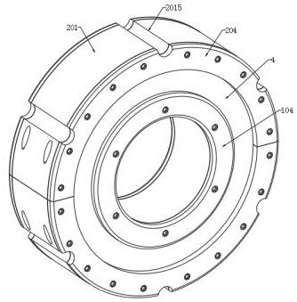
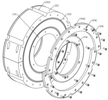
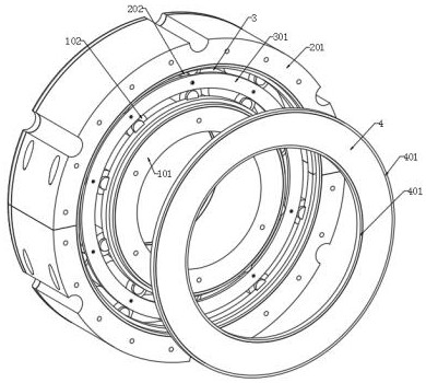
[0033] The present invention proposes a cylindrical roller bearing for a planetary frame of a wind power generation gearbox with a stop groove, comprising: an inner ring body 1, an outer ring body 2, an inner spacer ring 3 and a sealing ring body 4;

[0034] The inner ring body 1 is clamped on the inner side of the outer ring body 2, and the inner ends of the inner ring body 1 and the outer ring body 2 are respectively rotated and fitted with a sealing ring body 4. The inner ring body 1 includes an inner ring ring 101 and cylindrical rollers. A102, the outer ring of the inner ring 101 is provided with an outer concave ring groove 1011, and ten sets of cylindrical rollers A102 are rotated in the outer concave ring groove 1011, and the outer ring body 2 includes a semicircular plate 201 and cylindrical rollers B202, There are two groups of semicircular plates 201, and inner grooves 2011 are respectively arranged on the i...


PUM


Abstract

The invention provides a wind power generation speed-increasing gearbox planet carrier cylindrical roller bearing with a stop groove, and relates to the technical field of bearings, wherein the wind power generation speed-increasing gearbox planet carrier cylindrical roller bearing comprises an inner ring body, an outer ring body, an inner space ring and a sealing ring body; the inner ring body comprises an inner ring and cylindrical rollers A, an outer ring of the inner ring is provided with an outer concave ring groove, and ten groups of cylindrical rollers A are rotatably mounted in the outer concave ring groove; the outer ring body comprises two groups of semicircular plates and cylindrical rollers B, inner rings of the semicircular plates are respectively provided with inner grooves, and five groups of cylindrical rollers B are rotatably arranged in the inner grooves respectively; and the two semicircular plates are in butt joint and are connected in the mode that bolt rods penetrate through threaded through holes to form an outer ring, the cylindrical rollers A are opposite to the cylindrical rollers B, and the inner space ring is further inserted between the cylindrical rollers A and the cylindrical rollers B. When a group of cylindrical rollers or a circle of cylindrical rollers are damaged, the use of the bearing is not influenced, and a better sealing effect can be achieved. The problem that the use of the bearing is affected due to the damage of a group of internal cylindrical rollers is solved.

Description

technical field [0001] The invention relates to the technical field of bearings, in particular to a cylindrical roller bearing for a planet carrier of a wind power generation gearbox with a stop groove. Background technique [0002] The wind power gearbox is the core component of the wind power generator. Its function is to increase the lower speed transmitted by the rotating blades to the rated speed of the generator. in the gearbox. At present, the wind power planetary carrier bearing generally adopts the cylindrical roller bearing structure. With the continuous increase of the design power of the fan, the bearing is one of the weakest links of the gearbox. Due to the complex and very harsh working environment of the fan, under the condition of compound load , the existing bearing wears seriously during use and has a low service life. [0003] However, in current bearings, a group of cylindrical rollers inside are damaged, which affects the use of the bearing, and the lu...

Claims


Application Information

Patent Timeline
IPC IPC(8): F16C19/34F16C33/58F16C33/78F16C33/30
CPCF16C19/34F16C33/583F16C33/7816F16C33/30
Inventor 张耘赫马连祥马露薇
Owner 山东精派轴承科技有限公司
Learn More