Temperature control pressure relief plug for hydraulic coupler

A hydraulic coupler and coupler technology, applied in the direction of functional valve type, fluid transmission device, safety valve, etc., can solve problems such as affecting work efficiency, restricting pressure relief speed, easy to hurt people, etc., to reduce equipment repair time. , The effect of ensuring work efficiency and reducing the cost of use

Inactive Publication Date: 2022-02-08
程向华
View PDF0 Cites 0 Cited by
  • Summary
  • Abstract
  • Description
  • Claims
  • Application Information

AI Technical Summary

Problems solved by technology

[0003] In many scenarios, due to the harsh environment and frequent overloading, the phenomenon of fusible plug melting and spraying occurs more frequently. After the fusible plug is released, it needs to be shut down and replaced before it can continue to be used, which greatly affects work efficiency.
[0004] Secondly, as far as the fusible plug itself is concerned, due to the low strength of the fusible metal itself, the pressure relief area of ​​the fusible plug is usually small, which restricts the pressure relief speed, and the too small pressure relief area also increases the liquid injection pressure. , is more likely to hurt people, and further, affected by ingredients, pouring, thickness dimensions and melting time, only range control can be performed but fixed-point temperature control can not be achieved, which also reduces the operability of hydraulic coupling products

Method used


Image

  • Temperature control pressure relief plug for hydraulic coupler
  • Temperature control pressure relief plug for hydraulic coupler
  • Temperature control pressure relief plug for hydraulic coupler

Examples


Embodiment Construction

[0019] The following will clearly and completely describe the technical solutions in the embodiments of the present invention with reference to the accompanying drawings in the embodiments of the present invention. Obviously, the described embodiments are only some, not all, embodiments of the present invention. Based on the embodiments of the present invention, all other embodiments obtained by persons of ordinary skill in the art without making creative efforts belong to the protection scope of the present invention.

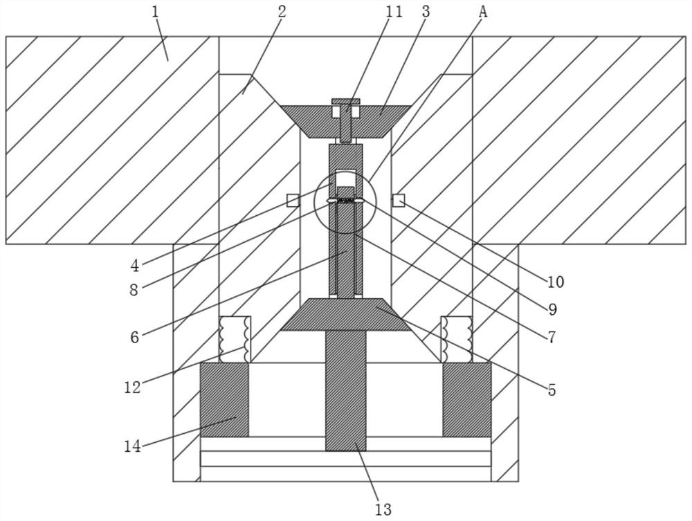
[0020] see figure 1 , a temperature-controlled pressure relief plug for a hydraulic coupling, including a housing 1 for installation on the coupler shell, sealing treatment between the housing 1 and the coupler, the inner wall of the housing 1 is connected with a The connecting seat 2 of the channel, the outer wall of the housing 1 is sealed with the housing 1, the connecting seat 2 is movably connected with an outer sealing plug 3 and an inner sealing plug 5 ...


PUM


Abstract

The invention relates to the technical field of safety valve equipment, and discloses a temperature control pressure relief plug for a hydraulic coupler. The pressure relief plug comprises a shell used for being mounted on a coupler shell, the inner wall of the shell is connected with a connecting seat with a channel, and the connecting seat is movably connected with an outer sealing plug and an inner sealing plug which are used for plugging the channel of the connecting seat. According to the temperature control pressure relief plug for the hydraulic coupler, locking is conducted through magnetic force of a ferromagnetic material, after high-temperature triggering pressure relief is conducted, when the normal temperature is recovered, the magnetic force is recovered, the pressure relief plug can be sealed again through pressing, the equipment repairing time is shortened, continuous production and machining are guaranteed, and further, due to the fact that replacement is reduced, the use cost is reduced; and secondly, the magnetic force is used for maintaining locking, and the direction of the magnetic force is perpendicular to the acting force generation direction, so that the locking can be maintained by the smaller magnetic force level, namely, the larger pressure relief area can be maintained by the smaller magnetic force level, and the pressure relief channel can be flexibly arranged according to actual requirements.

Description

technical field [0001] The invention relates to the technical field of safety valve equipment, in particular to a temperature-controlled pressure relief plug for a hydraulic coupler. Background technique [0002] The hydraulic coupling is usually equipped with a fusible plug. When the oil temperature is too high, the fusible plug melts, the channel opens, the oil sprays out from the through hole, and the power transmission is cut off, thereby avoiding the overload of the motor and the damage of the coupler due to overpressure. [0003] In many scenarios, due to the harsh environment and frequent overloading, the phenomenon of fusible plug melting and spraying occurs more frequently. After the fusible plug is released, it needs to be shut down and replaced before it can continue to be used, which greatly affects work efficiency. . [0004] Secondly, as far as the fusible plug itself is concerned, due to the low strength of the fusible metal itself, the pressure relief area o...

Claims


Application Information

Patent Timeline
Patent Type & Authority Applications(China)
IPC IPC(8): F16H41/24F16K17/38
CPCF16H41/24F16K17/38
Inventor 程向华
Owner 程向华
Why Eureka
Try Eureka