Unlock instant, AI-driven research and patent intelligence for your innovation.

A modulator and modulation method for radio frequency signal modulation enhancement

A technology of radio frequency signal and modulation method, which is applied in the coupling of instruments, optical waveguides, optics, etc., and can solve the problems of weakening modulation intensity and so on.

Active Publication Date: 2022-03-29
成都明夷电子科技有限公司
View PDF29 Cites 0 Cited by
  • Summary
  • Abstract
  • Description
  • Claims
  • Application Information

AI Technical Summary

Problems solved by technology

Even if the modulation signal is a periodic high-frequency analog (radio frequency) signal, continue to assume that the delay characteristics of the mirror can be ignored, and the mirror is considered to be an ideal immediate reflection. Because the direction of photoelectric propagation in the loop is opposite, the modulation intensity is the corresponding length The integration of the electrical signal amplitude, so the modulation intensity will be weakened at this stage

Method used


Image

  • A modulator and modulation method for radio frequency signal modulation enhancement
  • A modulator and modulation method for radio frequency signal modulation enhancement
  • A modulator and modulation method for radio frequency signal modulation enhancement

Examples


Embodiment 1

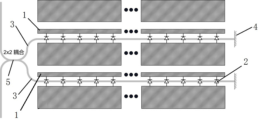
[0037] This embodiment proposes a modulator for radio frequency signal modulation enhancement, such as figure 1 As shown, the modulator includes a static phase shifter, a 2x2 coupling unit 5, a waveguide 3, and a waveguide terminal reflection unit 4;

[0038] The waveguide 3 is set in four groups, respectively lapped on the four ports of the 2x2 coupling unit 5 to form four waveguide channels; the two waveguide channels located on any side of the 2x2 coupling unit 5 and on the same side are respectively connected to a waveguide terminal reflection unit 4;

[0039] The two waveguide channels connected to the waveguide terminal reflection unit are respectively provided with transmission line electrodes; waveguide phase shifters are arranged on the waveguides of the two waveguide channels connected to the waveguide terminal reflection unit, and one end of the waveguide phase shifter is connected to the corresponding The transmission line electrode is connected, and the other end...

Embodiment 2

[0048] This embodiment is on the basis of above-mentioned embodiment 1, as figure 2 As shown, in order to better realize the present invention, further, the waveguide terminal reflection unit 4 includes a 1X2 multimode interferometer 6;

[0049] The delay waveguide module includes a first delay waveguide and a second delay waveguide;

[0050] Port 1 of the 1X2 multimode interferometer 6 is connected to a waveguide channel with a waveguide phase shifter 2 through a first delay waveguide; port 2 of the 1X2 multimode interferometer 6 is connected together to form a A ring waveguide of a loop; the second delay waveguide is arranged on the ring waveguide.

[0051] Working principle: A 1X2 multimode interferometer 6 and a ring waveguide forming a loop at the 2 ports are used to complete the mirror structure. When it is necessary to add a delay characteristic to the mirror, the waveguide length of the first delay waveguide or the second delay waveguide can be increased to control ...

Embodiment 3

[0054] This embodiment proposes a modulation method for radio frequency signal modulation enhancement, based on the aforementioned modulator for radio frequency signal modulation enhancement, specifically including the following steps:

[0055] Step 1: Receive signals through the waveguide channel on the side of the 2x2 coupling unit 5 that is not connected to the waveguide terminal reflection unit 4, and enter the waveguide phase shifter 2 for the first phase shift modulation after being split by the 2x2 coupling unit 5;

[0056] Step 2: Select whether delay processing is required according to actual needs;

[0057] Step 3: For those that do not require delay processing, use the waveguide terminal reflection unit 4 to reflect immediately, perform the second phase shift modulation through the waveguide phase shifter 2, and couple and shape the optical signal through the 2x2 coupling unit 5 and output it;

[0058] For those that require delay processing, select the delay length...


PUM


Abstract

The present invention proposes a modulator and a modulating method for radio frequency signal modulation enhancement, the modulator includes a static phase shifter, a 2x2 coupling unit, a waveguide, and a waveguide terminal reflection unit; the waveguide is set in four groups, respectively Connect to the four ports of the 2x2 coupling unit to form four waveguide channels; the two waveguide channels located on any side of the 2x2 coupling unit and on the same side are respectively connected to a waveguide terminal reflection unit; two waveguide terminal reflection units connected to the waveguide terminal reflection unit Each waveguide channel also includes two transmission line electrodes; a waveguide phase shifter is arranged on the waveguides of the two waveguide channels connected to the waveguide terminal reflection unit, and the two ends of the waveguide phase shifter are respectively connected to the two transmission line electrodes; An adjustable delay waveguide module is arranged on the reflection unit of the waveguide terminal; the static phase shifter is arranged on the modulator at any position before the waveguide phase shifter under the electrode of the transmission line.

Description

technical field [0001] The invention belongs to the technical field of communication signal modulation, and in particular relates to a modulator and a modulation method used for radio frequency signal modulation enhancement. Background technique [0002] In order to improve the modulation efficiency of broadband modulators and reduce the device size, one solution that silicon photonic platforms can use is the Michelson interferometer modulator structure. As an example, a model of a carrier-depleted silicon photonic Michelson interferometer modulator is shown in figure 1 . [0003] If the silicon photonic Michelson interferometer modulator is mirrored and docked with the waveguide terminal mirror as the midpoint, its optoelectronic structure will be basically the same as that of a silicon photonic McJanda modulator. In the Michelson interferometer modulator, since the mirror will reflect the light back into the original waveguide, the light undergoes two modulations of the ...

Claims


Application Information

Patent Timeline
Patent Type & Authority Patents(China)
IPC IPC(8): G02B6/28
CPCG02B6/2813G02B6/2861
Inventor 刘晟昊陶蕤王睿李广生赵欣
Owner 成都明夷电子科技有限公司
Features
  • R&D
  • Intellectual Property
  • Life Sciences
  • Materials
  • Tech Scout
  • Unparalleled Data Quality
  • Higher Quality Content
  • 60% Fewer Hallucinations
Learn More