
Insulator binding wire removal tool

A technology for dismantling tools and binding wires, which is applied in the direction of overhead lines/cable equipment, etc., can solve the problems of safety hazards in wearing insulating protective tools, difficulty and intensity of operations for operators, and cumbersome preparations for operators, so as to improve operation efficiency and operation The degree of standardization, the improvement of operational safety, and the effect of improving operational safety

Active Publication Date: 2022-05-03
国网瑞嘉(天津)智能机器人有限公司
View PDF9 Cites 0 Cited by
  • Summary
  • Abstract
  • Description
  • Claims
  • Application Information

AI Technical Summary

Problems solved by technology

[0003] The existing manual removal of insulator binding wires has at least the following methods: 1) The shielding work within the working range is complicated, and accidents are likely to occur if the shielding work is not perfect; Potential safety hazard; 3) The existing method of manual removal of insulator binding wires requires the coordinated combination of multiple tools, the removal operation is complicated, and it is inconvenient to work at heights; 4) The existing manual removal of the old binding wires needs to be unwound while unwinding, and the binding wires are broken during operation It is easy to puncture insulating gloves, and the operation is difficult and strong for operators, and the operation efficiency is low.

Method used


Image

  • Insulator binding wire removal tool
  • Insulator binding wire removal tool
  • Insulator binding wire removal tool

Examples


Embodiment Construction

[0032] In order to make the purpose, technical solutions and advantages of the embodiments of the present invention clearer, the technical solutions in the embodiments of the present invention will be clearly and completely described below in conjunction with the drawings in the embodiments of the present invention. Obviously, the described embodiments It is a part of embodiments of the present invention, but not all embodiments. The components of the embodiments of the invention generally described and illustrated in the figures herein may be arranged and designed in a variety of different configurations.

[0033] Accordingly, the following detailed description of the embodiments of the invention provided in the accompanying drawings is not intended to limit the scope of the claimed invention, but merely represents selected embodiments of the invention. Based on the embodiments of the present invention, all other embodiments obtained by persons of ordinary skill in the art wi...


PUM


Abstract

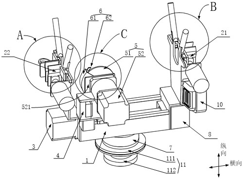
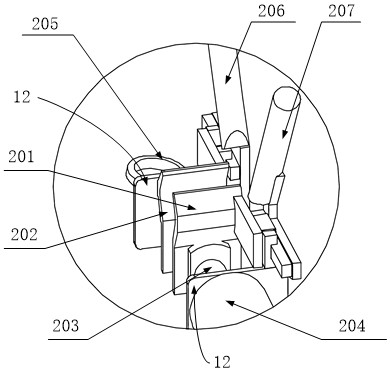
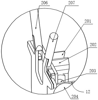
The invention provides a tool for removing insulator binding wires, which relates to the technical field of electric power construction, and includes a support frame, a wire holding mechanism, a lateral movement mechanism, a longitudinal movement mechanism, and a grinding wheel rotation drive mechanism; the wire holding mechanism is connected to the support frame, and is used for Clamp or release the wire; the grinding wheel rotation drive mechanism includes a rotation drive transmission part and a grinding wheel connected to the rotation drive transmission part, the rotation drive transmission part can drive the grinding wheel to rotate; the rotation drive transmission part is connected to the longitudinal movement mechanism, and the longitudinal movement mechanism is connected to the transverse The moving mechanism and the lateral moving mechanism are connected to the supporting frame; the lateral moving mechanism can drive the longitudinal moving mechanism to move laterally, and the longitudinal moving mechanism can drive the rotating drive transmission part to move longitudinally; the supporting frame is provided with an installation connection part for connecting the mechanical arm. The invention simplifies the operation process of removing the insulator binding wires, improves the removal efficiency of the insulator binding wires, and simultaneously improves the operating safety of operators.

Description

technical field [0001] The invention relates to the technical field of electric power construction, in particular to a tool for removing insulator binding wires. Background technique [0002] In the technical field of electric power construction, the existing methods of dismantling the binding wires of pin-type insulators are manual dismantling, and operators must wear complete personal insulation protection tools, fasten their safety belts and work in the insulated bucket arm bucket. During operation, it is necessary to shield live wires, insulators, metal cross-arms, etc. within the scope of work. When removing old binding wires, it is necessary to untie them while unrolling them. The broken part of the binding wire punctured the insulating gloves. [0003] The existing manual removal of insulator binding wires has at least the following methods: 1) The shielding work within the working range is complicated, and accidents are likely to occur if the shielding work is not p...

Claims


Application Information

Patent Timeline
Patent Type & Authority Patents(China)
IPC IPC(8): H02G1/02
CPCH02G1/02
Inventor 任建超李帅王朝松黄耀尉文
Owner 国网瑞嘉(天津)智能机器人有限公司
Learn More