Ship direct-current cable laying structure

A DC cable, ship technology, applied in cable laying equipment, electrical components and other directions, can solve problems affecting the operation of its own equipment, affecting the operation of electronic equipment, affecting the operation of ship electrical equipment, etc., to achieve the effect of eliminating electromagnetic interference

Pending Publication Date: 2022-02-08
AFAI SOUTHERN SHIPYARDPANYU GUANGZHOU LTD
View PDF0 Cites 0 Cited by
  • Summary
  • Abstract
  • Description
  • Claims
  • Application Information

AI Technical Summary

Problems solved by technology

[0002] With the global promotion of the use of environmentally friendly materials and new energy, the application of hybrid propulsion ships, pure electric propulsion ships, and DC network electric propulsion ships is becoming more and more extensive. The safety and stability of the propulsion power distribution system and propulsion control system It is particularly important for electric propulsion ships, because electric propulsion ships involve the laying of a large number of power cables, communication cables, and control cables. However, according to the traditional cable laying process, during the ship commissioning stage, the cables have different degrees of mutual electromagnetic interference. Interference, on the one hand, affects the operation of its own equipment, and on the other hand, affects the operation of other electronic equipment on board. What's more, the electromagnetic interference between cables in the DC network affects the operation of electrical equipment on nearby ships.

Method used


Image

  • Ship direct-current cable laying structure
  • Ship direct-current cable laying structure

Examples


Embodiment 1

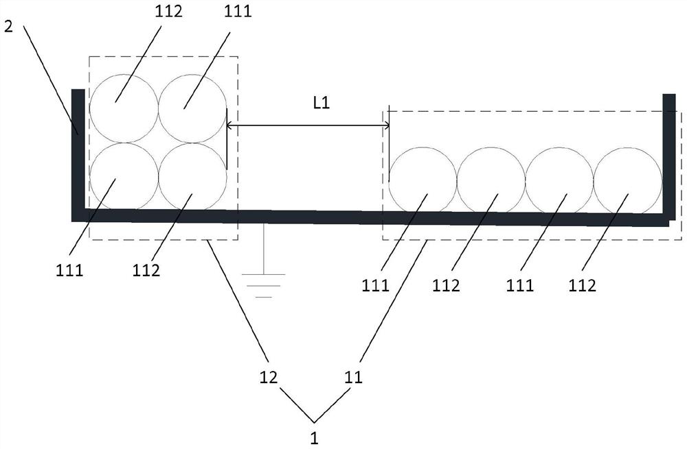
[0035] figure 1 It is a structural schematic diagram of the ship DC cable laying structure shown in the embodiment of the present application.

[0036] see figure 1 , the ship's DC cable laying structure includes a propulsion power cable bundle 1 and a cable bracket 2, the propulsion power cable bundle 1 includes a first propulsion power cable bundle 11, and the first propulsion power cable bundle 11 includes at least two groups of DC cable bundles, each group The DC cable bundle includes a positive DC cable 111 and a negative DC cable 112, and each group of DC cable bundles is laid side by side in the order of arrangement from the positive DC cable 111 to the negative DC cable 112, or from the negative DC cable 112 to the positive DC cable 111. On the cable tray 2, two adjacent groups of DC cable bundles are close to each other and arranged in the same order.

[0037] In this embodiment, the laying method of the first propulsion power cable bundle 11 on the cable bracket 2 ...

Embodiment 2

[0042] In practical applications, on the basis of the first embodiment, each group of DC cable bundles can also be stacked on top of each other.

[0043] see figure 1The propulsion power cable bundle 1 also includes a second propulsion power cable bundle 12, the second propulsion power cable bundle 12 includes at least two groups of DC cable bundles, and each group of DC cable bundles is arranged according to the order of positive DC cables 111 to negative DC cables 112, Or the negative DC cable 112 to the positive DC cable 111 are arranged side by side and stacked on the cable bracket 2 , two adjacent DC cable bundles are close to each other and the arrangement sequence is reversed.

[0044] In this embodiment, the laying method of the second propulsion power cable bundle 12 on the cable bracket 2 is as follows: the positive DC cables 111 and the negative DC cables 112 in the first group of DC cable bundles are laid sequentially on the bottom layer, and the second The DC cab...

Embodiment 3

[0050] In practical applications, on the basis of the above embodiments, in order to prevent electromagnetic interference between the propulsion power cable bundles, a certain distance needs to be kept between the propulsion power cable bundles.

[0051] see figure 1 , the distance L1 between the first propulsion power cable bundle 11 and the second propulsion power cable bundle 12 is greater than 20 mm.

[0052] It should be noted that each propulsion power cable bundle 1 may only include one or more first propulsion power cable bundles 11 or second propulsion power cable bundles 12, or may include first propulsion power cable bundles 11 and second propulsion power cable bundles 12. The combination of the cable bundles 12 is not limited here. In this embodiment, the propulsion power cable bundle 1 includes a first propulsion power cable bundle 11 and a second propulsion power cable bundle 12 .

[0053] In addition, when there are only first propulsion power cable bundles 11 ...


PUM


Abstract

The invention relates to a ship direct-current cable laying structure. The structure comprises a propelling power cable bundle and a cable bracket, the propelling power cable bundle includes a first propelling power cable bundle; the first propelling power cable bundle comprises at least two sets of direct-current cable bundles; each set of direct-current cable bundle comprises an anode direct-current cable and a cathode direct-current cable; each set of direct-current cable bundle is flatly laid on the cable bracket side by side according to an arrangement sequence from the positive direct-current cable to the negative direct-current cable or an arrangement sequence from the negative direct-current cable to the positive direct-current cable; and two adjacent sets of direct-current cable bundles abut against each other and are arranged in the same sequence. According to the ship direct-current cable laying structure provided by the invention, mutual electromagnetic interference generated between direct-current electric propelling ship cables can be reduced, and adverse effects of the electromagnetic interference on ship equipment and nearby ship equipment are avoided.

Description

technical field [0001] The present application relates to the technical field of cable laying, in particular to a ship direct current cable laying structure. Background technique [0002] With the global promotion of the use of environmentally friendly materials and new energy, the application of hybrid propulsion ships, pure electric propulsion ships, and DC network electric propulsion ships is becoming more and more extensive. The safety and stability of the propulsion power distribution system and propulsion control system It is particularly important for electric propulsion ships, because electric propulsion ships involve the laying of a large number of power cables, communication cables, and control cables. However, according to the traditional cable laying process, during the ship commissioning stage, the cables have different degrees of mutual electromagnetic interference. Interference, on the one hand, affects the operation of its own equipment, and on the other hand...

Claims


Application Information

Patent Timeline
IPC IPC(8): H02G3/04H02G1/06
CPCH02G3/04H02G1/06
Inventor 曾翠梅万静盘小川廖强
Owner AFAI SOUTHERN SHIPYARDPANYU GUANGZHOU LTD
Why Eureka
Try Eureka