
Slidable critical patient transfer instrument rack

A sliding, critical technology, used in stretchers, medical transportation, transportation and packaging, etc., can solve the problems of cumbersome operation steps, inconvenient placement of instruments and infusion bags, and inability to ensure the safety of instruments and equipment.

Pending Publication Date: 2022-02-11
青岛山大齐鲁医院(山东大学齐鲁医院(青岛))
View PDF0 Cites 1 Cited by
  • Summary
  • Abstract
  • Description
  • Claims
  • Application Information

AI Technical Summary

Problems solved by technology

[0004] The purpose of the present invention is to provide a slidable critical patient transfer instrument rack to solve the problem in the above-mentioned background art that the transfer instrument rack is inconvenient to place instruments due to the need to use some instruments and equipment or the liquid being infused during the transfer. Equipment and infusion bags; because there are no fixed parts, the equipment may fall during the transfer process, and the safety of the equipment cannot be guaranteed: the current transfer equipment rack requires more people during transportation, so it may cause hospital beds It is inconvenient to carry in the limited space above; the current transfer instrument rack cannot directly translate the transfer instrument rack to another hospital bed, resulting in cumbersome operation steps; the overall stability of the current transfer instrument rack is not high. The safety is not high; it is not convenient to integrate the pipeline lines, which leads to the confusion of the instrument rack

Method used


Image

  • Slidable critical patient transfer instrument rack
  • Slidable critical patient transfer instrument rack
  • Slidable critical patient transfer instrument rack

Examples


Embodiment Construction

[0030] The following will clearly and completely describe the technical solutions in the embodiments of the present invention with reference to the accompanying drawings in the embodiments of the present invention. Obviously, the described embodiments are only some, not all, embodiments of the present invention. Based on the embodiments of the present invention, all other embodiments obtained by persons of ordinary skill in the art without making creative efforts belong to the protection scope of the present invention.

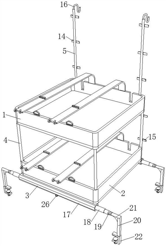
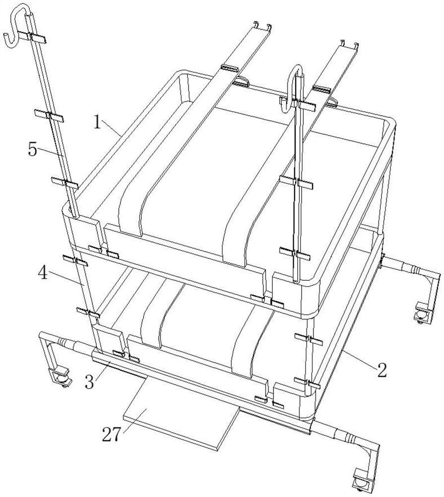
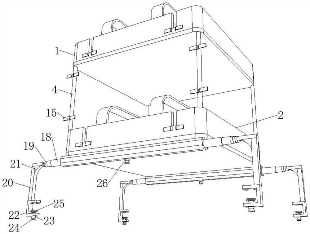
[0031] see Figure 1-6 , the present invention provides a slidable transport instrument rack for critically ill patients, comprising an upper object table 1, a lower object table 2, a transfer member 3, four connecting rods 4 and two infusion rods 5, an upper object table 1 and a lower object table Platform 2 all comprises loading plate 6, and the four sides of the upper surface of loading plate 6 are all fixedly provided with protective plate 7, and the top o...


PUM


Abstract

The invention discloses a slidable critical patient transfer instrument rack, and relates to the technical field of medical instruments. The slidable critical patient transfer instrument rack comprises an upper objective table, a lower objective table, a transfer piece, four connecting rods and two infusion rods, the upper objective table and the lower objective table each comprise an objective plate, protection plates are fixedly arranged on the four edges of the upper surface of each objective plate, and two fixing belts are fixedly arranged at the top end of each protection plate on the rear side. By arranging the upper objective table and the lower objective table, and arranging the objective plates and the protective plates on the upper objective table and the lower objective table, instruments and equipment used by a patient can be stably supported, an infusion bag used by the patient can be suspended and supported through the cooperation of an infusion rod and an infusion bag hook, therefore, the problem that instruments and equipment or infusion bags are inconvenient to place on the transfer instrument rack due to the fact that some instruments and equipment or infusion liquid is needed during transfer is solved.

Description

technical field [0001] The invention relates to a transport instrument rack, in particular to a slidable transport instrument rack for critically ill patients. Background technique [0002] When patients need to go out for examination or transfer to another department, these instruments and equipment will be placed on the bed. Due to the limited area of ​​the hospital bed unit, it will cause inconvenience in storing the equipment and equipment, and it may also cause damage to the equipment, and some patients with drug-resistant bacteria are also prone to To pollute the instrument, although there are already some instrument transfer racks in the prior art, the instrument can be placed on it to avoid placing the instrument on the bed, but the current transfer instrument rack still has the following problems: [0003] 1. Due to the need to use some instruments and equipment or the liquid being infused during the transfer, it is not convenient to place the instruments and infusi...

Claims


Application Information

Patent Timeline
Patent Type & Authority Applications(China)
IPC IPC(8): A61G1/04A61G7/05A61M5/14A61M25/02H02G3/04
CPCA61G1/04A61G7/05A61M5/1415A61M5/1417A61M25/02H02G3/0406H02G3/0462A61M2025/0253
Inventor 王艳朱超奇张新王延红孙恒康张宝贵孙义栋
Owner 青岛山大齐鲁医院(山东大学齐鲁医院(青岛))
Learn More