A flight route design method based on aerial remote sensing system

An aviation remote sensing and flight route technology, applied in the field of remote sensing and navigation, can solve the problems of reduced flight efficiency, redundant flight routes and flight time, etc., achieve the effect of reducing flight routes, avoiding redundant flights, and improving operational efficiency

Active Publication Date: 2022-04-08
AEROSPACE INFORMATION RES INST CAS
View PDF5 Cites 0 Cited by
  • Summary
  • Abstract
  • Description
  • Claims
  • Application Information

AI Technical Summary

Problems solved by technology

Since the functions and principles of the above-mentioned remote sensing devices are different, and the corresponding technical parameters are also different, the index requirements of each remote sensing device are different, so it is difficult to ensure that each remote sensing device is Remote sensing equipment can meet their respective index requirements, which leads to remote sensing aircraft needing to fly multiple routes and constantly change flight altitudes to make up for the differences caused by different index requirements, which will lead to redundancy in flight sorties, flight routes, and flight time. reduction in flight efficiency

Method used


Image

  • A flight route design method based on aerial remote sensing system
  • A flight route design method based on aerial remote sensing system
  • A flight route design method based on aerial remote sensing system

Examples


Embodiment Construction

[0021] The technical solutions in the embodiments of the present invention will be clearly and completely described below in conjunction with the accompanying drawings in the embodiments of the present invention. Obviously, the described embodiments are only part of the embodiments of the present invention, not all of them. Based on the embodiments of the present invention, all other embodiments obtained by persons of ordinary skill in the art without making creative efforts belong to the protection scope of the present invention.

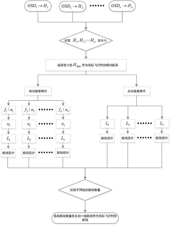
[0022] see figure 1 , according to an embodiment of the present invention, a flight route design method based on the aerial remote sensing system is proposed, and calculation is performed according to the known parameters of different remote sensing devices in the aerial remote sensing system, and various equivalent new parameters are obtained, and then a unified The flight route plan, while meeting the requirements of different remote sensing equi...


PUM


Abstract

The invention relates to a flight route design method based on an aviation remote sensing system, comprising the following steps: step 1) calculating the relative altitude of different aerial remote sensing equipment; step 2) confirming the relative altitude during the final actual flight; step 3) calculating the focal length The ratio of CCD pixel size; Step 4) Calculate the number of equivalent lateral CCDs; Step 5) Calculate the lateral coverage width of the image on the ground; Step 6) Design the flight route and determine the final actual flight route. The invention calculates according to the known parameters of different remote sensing devices in the aerial remote sensing system, obtains various equivalent new parameters, and then generates a unified flight route plan, and realizes the measurement of different remote sensing devices under the condition that the requirements of different remote sensing devices are met at the same time. Therefore, the operation efficiency can be improved and repeated operations can be reduced.

Description

technical field [0001] The invention relates to the field of remote sensing and navigation, in particular to a flight route design method. Background technique [0002] The aerial remote sensing system is to integrate various earth observation loads on an aircraft, and realize earth observation through aviation flight. The remote sensing aircraft has advanced technical indicators, is capable of all-weather flight operations, and can be loaded with various remote sensors such as aerial cameras, imaging spectrometers, and imaging radars. Remote sensing aircraft have played an important role in remote sensing comprehensive application experiments, major natural disaster monitoring, and independent research and development of remote sensing equipment. [0003] The remote sensing equipment loaded in the aerial remote sensing system is divided into passive remote sensing equipment and active remote sensing equipment. Passive remote sensing, also known as passive remote sensing s...

Claims


Application Information

Patent Timeline
Patent Type & Authority Patents(China)
IPC IPC(8): G01C21/20G01C11/00
CPCG01C21/20G01C11/00
Inventor 吴亮刘玉泉朱金彪潘洁汤洪彪
Owner AEROSPACE INFORMATION RES INST CAS
Why Eureka
Try Eureka