Pressurized water reactor core flow and power four-zone control method

A technology of zone control and flow zone, which is applied in the field of nuclear reactor core, can solve the problems of difficult power distribution and flow control process, matching deviation of power distribution and flow control, and reduce the extreme value of hot channel temperature, so as to improve thermal safety Margin, reduced hot aisle temperature extremes, effect of increased coolant temperature

Pending Publication Date: 2022-02-11
NUCLEAR POWER INSTITUTE OF CHINA
View PDF1 Cites 0 Cited by
  • Summary
  • Abstract
  • Description
  • Claims
  • Application Information

AI Technical Summary

Problems solved by technology

[0004] However, the existing three-zone PWR core flow design still has certain deviations in power distribution and flow control matching, which is not conducive to reducing the extreme temperature of the hot channel and improving the thermal safety margin of the core. The actual power Difficulty in distribution and flow control process

Method used


Image

  • Pressurized water reactor core flow and power four-zone control method
  • Pressurized water reactor core flow and power four-zone control method

Examples


Embodiment 1

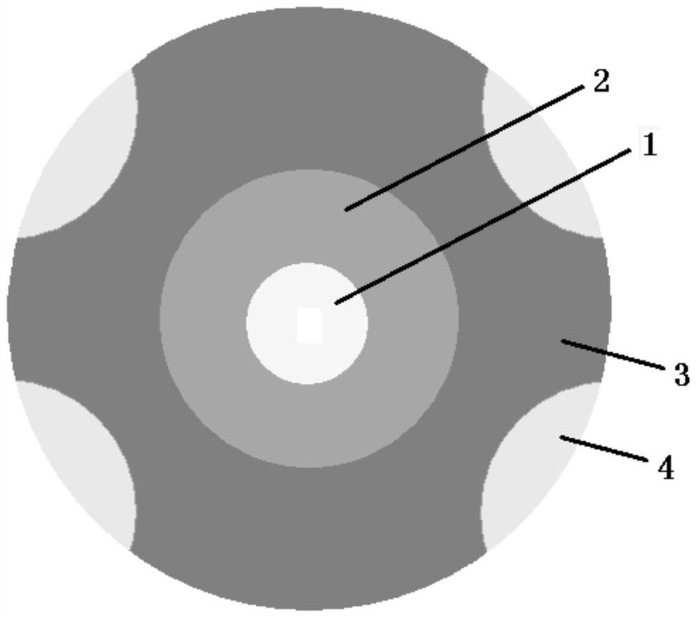
[0042] A four-zone control method for core flow and power in a pressurized water reactor, such as figure 1 As shown in the figure, the transverse section of the PWR core expands radially outwards and is sequentially provided with a first flow area 1, a second flow area 2, and a third flow area 3, the second flow area 2 wraps the first flow area 1, The third flow zone 3 surrounds the second flow zone 2 . Four fourth flow regions 4 are arranged at intervals on the edge of the third flow region 3 , and the fourth flow regions 4 are embedded toward the center of the third flow region 3 . The flow rate of the coolant in the second flow area 2 is greater than the flow rate of the coolant in the first flow area 1, the flow rate of the coolant in the first flow area 1 is greater than the flow rate of the coolant in the third flow area 3, and the third flow area The flow rate of the coolant in the flow area 3 is greater than the flow rate of the coolant in the fourth flow area 4 . It...

Embodiment 2

[0051] The difference between Example 2 and Example 1 is that: the first flow area 1 passes into the coolant with an average mass flow rate of 100% of the entire PWR core; the second flow area 2 passes into the entire PWR core with an average mass flow rate The coolant with a flow rate of 110%; the third flow zone 3 passes into the coolant with an average mass flow rate of 95% of the entire PWR core; the fourth flow zone 4 passes into the coolant with an average mass flow rate of 90% of the entire PWR core .

Embodiment 3

[0053] The difference between Example 3 and Example 1 is that: the first flow area 1 is passed into the coolant with an average mass flow rate of 110% of the entire PWR core; the second flow area 2 is passed into the entire PWR core with an average mass flow rate The coolant with a flow rate of 120%; the third flow zone 3 passes into the coolant with an average mass flow rate of 100% of the entire PWR core; the fourth flow zone 4 passes into the coolant with an average mass flow rate of 95% of the entire PWR core .


PUM


Abstract

The invention discloses a pressurized water reactor core flow and power four-zone control method, and relates to the technical field of nuclear reactor cores. The method is characterized in that the cross section of a pressurized water reactor core is sequentially provided with a first flow zone, a second flow zone and a third flow zone in an outward expanding manner along the radial direction, the second flow zone wraps the first flow zone, the third flow zone wraps the second flow zone, a plurality of fourth flow zones are arranged on the edge of the third flow zone at intervals, and the fourth flow zones are embedded towards the center of the third flow zone. The flow of a coolant introduced into the second flow zone is larger than that of the coolant introduced into the first flow zone, the flow of the coolant introduced into the first flow zone is larger than that of the coolant introduced into the third flow zone, and the flow of the coolant introduced into the third flow zone is larger than that of the coolant introduced into the fourth flow zone. Through refined coordination matching design of related physics, hydraulics, structures and the like, stable distribution of the radial power of the reactor core and the matching degree of the radial power and the flow in the whole life period are achieved.

Description

technical field [0001] The invention relates to the technical field of nuclear reactor cores, and more particularly, to a four-division control method for the flow and power of a pressurized water reactor core. Background technique [0002] At present, non-pressurized water reactors such as fast reactors, boiling water reactors, supercritical water reactors, and heavy water reactors all adopt the technology of power partition and flow partition in the world, so as to realize the efficient utilization of core coolant. Under the same core power level, through the design of power partition and flow partition, the coolant flow required by the core can be reduced, or the thermal safety margin of the core can be improved, and the coolant temperature at the core outlet can be increased at the same time. In turn, the overall parameters and overall performance of the core are improved. For example, the core flow rate of the prototype fast reactor in India is divided into 15 areas, a...

Claims


Application Information

Patent Timeline
IPC IPC(8): G21C19/04G21C15/00
CPCG21C19/04G21C15/00Y02E30/30
Inventor 卢川杨雯何航行冉旭刘余邓坚于颖锐巨海涛李垣明张林黄慧剑辛素芳刘卢果倪东洋王连杰辛勇王浩煜刘松亚张吉斌李鹏飞付冉高希龙陈建国吕新知
Owner NUCLEAR POWER INSTITUTE OF CHINA
Why Eureka
Try Eureka