
Pressing-plate-free surface mounting device for circuit board

A patch device and circuit board technology, which is applied in the direction of assembling printed circuits with electrical components, can solve the problems of damaged circuit boards, low precision, and slow efficiency, and achieve the effect of ensuring stability and sensitive and rapid patching process

Pending Publication Date: 2022-02-11
四川和恩泰半导体有限公司
View PDF4 Cites 0 Cited by
  • Summary
  • Abstract
  • Description
  • Claims
  • Application Information

AI Technical Summary

Problems solved by technology

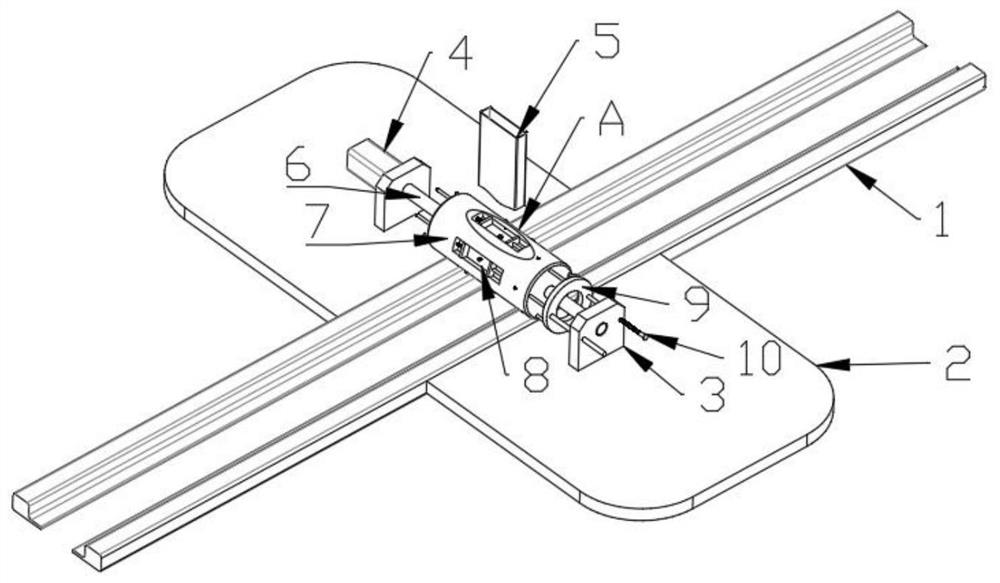
[0003] Among them, most of the circuit boards installed in industrial production equipment are traditional models, which are large in size, simple in installation process, and low in manufacturing cost. Most of the electronic components on the circuit board are arranged linearly and only need to be installed manually. Such circuit boards are common It is produced by workshop-style manual placement, but the process of manually placing electronic components is not only low in accuracy and slow in efficiency, but also has the problem of damaging the circuit board. Therefore, a circuit board without pressure plate placement device is needed

Method used


Image

  • Pressing-plate-free surface mounting device for circuit board
  • Pressing-plate-free surface mounting device for circuit board
  • Pressing-plate-free surface mounting device for circuit board

Examples


Embodiment Construction

[0026] In order to make the above objects, features and advantages of the present invention more comprehensible, specific implementations of the present invention will be described in detail below in conjunction with the accompanying drawings. In the following description, numerous specific details are set forth in order to provide a thorough understanding of the present invention. However, the present invention can be implemented in many other ways different from those described here, and those skilled in the art can make similar improvements without departing from the connotation of the present invention, so the present invention is not limited by the specific implementations disclosed below.

[0027] It should be noted that when an element is referred to as being “fixed” to another element, it can be directly on the other element or there can also be an intervening element. When an element is referred to as being "connected to" another element, it can be directly connected ...


PUM


Abstract

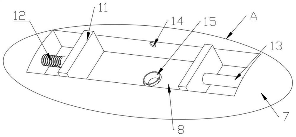
The invention discloses a circuit board patch device without a pressing plate, and relates to the technical field of circuit board processing. The circuit board patch device comprises an electric slide rail for conveying a circuit board, the two sides of the electric slide rail are fixedly connected with mounting platforms, the upper ends of the mounting platforms are fixedly connected with mounting seats, and a mounting shaft is rotatably connected between the two mounting seats. The mounting shaft is fixedly connected with a patch cylinder located above the electric sliding rail, the side wall of the mounting base is fixedly connected with a motor, the tail end of an output shaft of the motor is fixedly connected with the mounting shaft, the mounting platform is fixedly connected with a discharging cylinder located above the patch cylinder, and a plurality of clamping grooves distributed at equal intervals are formed in the side wall of the patch cylinder; two clamping pieces are arranged in the clamping groove, and an adjusting cavity is formed in the patch cylinder. According to the invention, the technical problem of how to carry out efficient surface mounting on the plate-shaped electronic device on the circuit board is solved.

Description

technical field [0001] The invention relates to the technical field of circuit board processing, in particular to a circuit board non-pressure plate mounting device. Background technique [0002] The circuit board is one of the most important electronic devices. From airplanes and cars to mobile phones and watches, circuit boards of various sizes and styles are installed inside them. According to the equipment to be installed and the functions to be realized, the circuit board is divided into single-sided boards. , double-sided panel and so on. [0003] Among them, most of the circuit boards installed in industrial production equipment are traditional models, which are large in size, simple in installation process, and low in manufacturing cost. Most of the electronic components on the circuit board are arranged linearly and only need to be installed manually. Such circuit boards are common It is produced for workshop-style manual placement, but the process of manually plac...

Claims


Application Information

Patent Timeline
Patent Type & Authority Applications(China)
IPC IPC(8): H05K3/30
CPCH05K3/30Y02W30/82
Inventor 王悦聪徐艺凌
Owner 四川和恩泰半导体有限公司
Learn More