Multi-pole magnetic ring progressive orientation mold and orientation method thereof
A multi-pole magnetic ring, progressive technology, used in the manufacture of inductors/transformers/magnets, electrical components, circuits, etc., can solve the problems of surface magnetic tool difference, large upper and lower pole difference, etc., to achieve consistent performance, convenient control and management , the effect of orientation is sufficient
- Summary
- Abstract
- Description
- Claims
- Application Information
AI Technical Summary
Problems solved by technology
Method used
Image

Examples
Embodiment 1
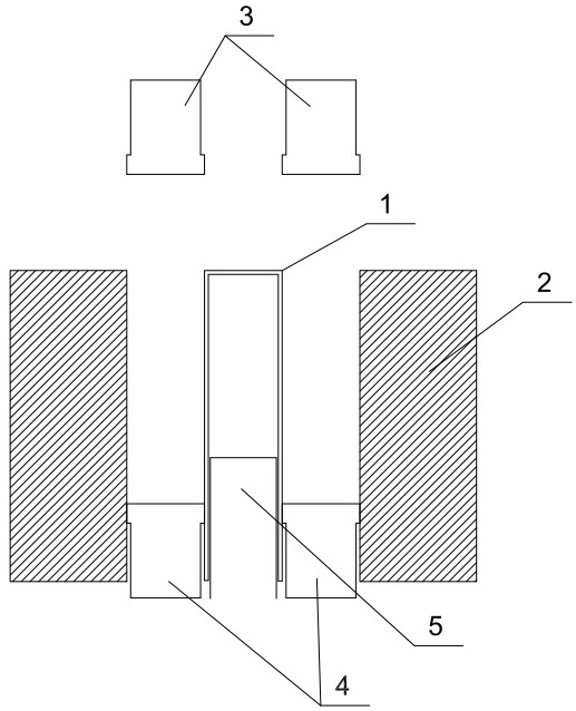
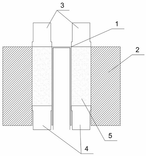
[0029] Such as Figure 1-Figure 2 As shown, the orientation step is a continuous process, Figure 1-2 It is only a schematic cut-out diagram of some representative orientation steps, and the specific orientation steps are based on the following description.
[0030] 1.1 Orientation mold
[0031] A kind of multi-pole magnetic ring progressive orientation mold provided by embodiment 1 comprises a mold core 1 and a mold sleeve 2 arranged outside the mold core 1, and there is an annular gap between the mold core 1 and the mold sleeve 2;
[0032] A cavity is provided in the mold core 1, and a movable orienter 5 is arranged in the cavity, and the orienter 5 is connected to a controller;
[0033] The upper end of the annular gap is provided with a matching upper pressure head 3, the lower end of the annular gap is provided with a matching lower pressure head 4, the outer wall of the mold core 1, the inner wall of the mold sleeve 2, the upper pressure head 3 The lower surface of th...
Embodiment 2
[0043] 2.1 Orientation mold
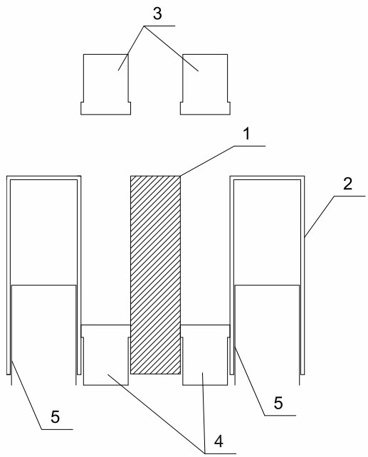
[0044] Such as image 3 as shown,
[0045] A progressive orientation mold for multi-pole magnetic rings provided in Embodiment 2 includes a mold core 1 and a mold sleeve 2 arranged outside the mold core 1, and there is an annular gap between the mold core 1 and the mold sleeve 2;
[0046] A cavity is provided in the mold cover 2, and a movable orienter 5 is arranged in the cavity, and the orienter 5 is connected to the controller;
[0047] The upper end of the annular gap is provided with a matching upper pressure head 3, the lower end of the annular gap is provided with a matching lower pressure head 4, the outer wall of the mold core 1, the inner wall of the mold sleeve 2, the upper pressure head 3 The lower surface of the lower surface and the upper surface of the lower pressure head 4 form a mold cavity.
[0048] As an optional implementation, the controller is a PLC controller.
[0049] As an optional implementation, the orienter 5 is a s...
Embodiment 3
[0057] 3.1 Orientation mold
[0058] A kind of multi-pole magnetic ring progressive orientation mold provided by embodiment 3 comprises a mold core 1 and a mold sleeve 2 arranged outside the mold core 1, and there is an annular gap between the mold core 1 and the mold sleeve 2;
[0059] Both the mold core 1 and the mold sleeve 2 are provided with a cavity, and a movable orienter 5 is arranged in the cavity, and the orienter 5 is connected to a controller;
[0060] The upper end of the annular gap is provided with an upper indenter 3 with a matching size, and the lower end of the annular gap is provided with a lower indenter 4 with a matching size. The lower surface of the lower surface and the upper surface of the lower pressure head 4 form a mold cavity.
[0061] As an optional implementation, the controller is a PLC controller.
[0062] As an optional implementation, the orienter 5 is a special orienter for multi-pole magnetic rings, and the number of poles of the special ...
PUM
| Property | Measurement | Unit |
|---|---|---|
| Height | aaaaa | aaaaa |
| Height | aaaaa | aaaaa |
Abstract
Description
Claims
Application Information
 - R&D
- Intellectual Property
- Life Sciences
- Materials
- Tech Scout
- Unparalleled Data Quality
- Higher Quality Content
- 60% Fewer Hallucinations
Browse by: Latest US Patents, China's latest patents, Technical Efficacy Thesaurus, Application Domain, Technology Topic, Popular Technical Reports.
© 2025 PatSnap. All rights reserved.Legal|Privacy policy|Modern Slavery Act Transparency Statement|Sitemap|About US| Contact US: help@patsnap.com