A progressive orientation mold for a multi-pole magnetic ring and its orientation method

A multi-pole magnetic ring, progressive technology, applied in the manufacture of inductors/transformers/magnets, electrical components, circuits, etc., can solve the problems of surface magnetic tool difference, large upper and lower pole difference, etc., to achieve consistent performance, convenient control and management , the effect of improving performance

Active Publication Date: 2022-04-22
绵阳和一磁电有限公司
View PDF11 Cites 0 Cited by
  • Summary
  • Abstract
  • Description
  • Claims
  • Application Information

AI Technical Summary

Problems solved by technology

[0005] The purpose of the present invention is to provide a progressive orientation mold for multi-pole magnetic rings and its orientation method to solve the technical problems that the products prepared by the orientation mold and the orientation method in the prior art have large upper and lower extreme differences and differences in surface magnetism

Method used


Image

  • A progressive orientation mold for a multi-pole magnetic ring and its orientation method
  • A progressive orientation mold for a multi-pole magnetic ring and its orientation method
  • A progressive orientation mold for a multi-pole magnetic ring and its orientation method

Examples


Embodiment 1

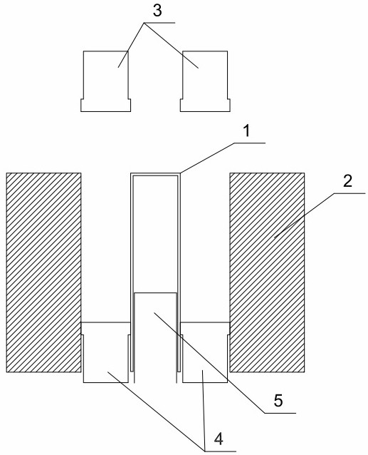
[0029] as Figure 1- Figure 2 As shown, the orientation step is a continuous process, Figure 1-2 It is only a screenshot of some representative orientation steps, and the specific orientation steps are described later.

[0030] 1.1 Orientation mold

[0031] Example 1 provides a multipolar magnetic ring progressive orientation die, comprising a die core 1 and a die sleeve 2 disposed on the outside of the die core 1, the die 1 has a toroidal gap between the die 1 and the die sleeve 2;

[0032] The die core 1 is provided with a cavity, the cavity is provided with a movable aligner 5, the aligner 5 and the controller is connected;

[0033] The upper end of the annular void is provided with a size matching upper indenter 3, the lower end of the annular void is provided with a size matching lower indenter 4, the outer wall of the die core 1, the inner wall of the mold sleeve 2, the lower surface of the upper indenter 3 and the upper surface of the lower indenter 4 form a mold cavity.

[00...

Embodiment 2

[0043] 2.1 Orientation mold

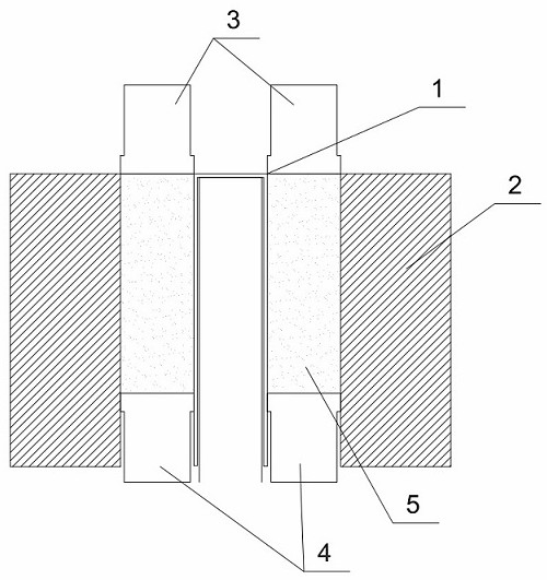
[0044] as Figure 3 as shown,

[0045] Example 2 provides a multipolar magnetic ring progressive orientation die, comprising a die core 1 and a die sleeve 2 disposed on the outside of the die core 1, the die 1 has a toroidal gap between the die 1 and the die sleeve 2;

[0046] The module sleeve 2 is provided with a cavity, the cavity is provided with a movable aligner 5, the aligner 5 and the controller connection;

[0047] The upper end of the annular void is provided with a size matching upper indenter 3, the lower end of the annular void is provided with a size matching lower indenter 4, the outer wall of the die core 1, the inner wall of the mold sleeve 2, the lower surface of the upper indenter 3 and the upper surface of the lower indenter 4 form a mold cavity.

[0048] As an alternative embodiment, the controller is a PLC controller.

[0049] As an alternative embodiment, the aligner 5 is a multipolar magnetic ring special aligner, the number of ...

Embodiment 3

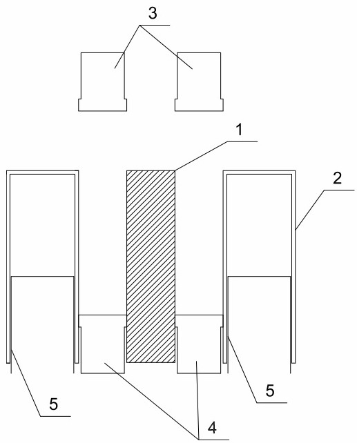
[0057] 3.1 Orientation mold

[0058] Example 3 provides a multipolar magnetic ring progressive orientation die, comprising a die core 1 and a die sleeve 2 disposed on the outside of the die core 1, the die 1 has a toroidal gap between the die 1 and the die sleeve 2;

[0059] The die core 1 and the die sleeve 2 are equipped with a cavity, the cavity is provided with a movable aligner 5, the oriented device 5 and the controller is connected;

[0060] The upper end of the annular void is provided with a size matching upper indenter 3, the lower end of the annular void is provided with a size matching lower indenter 4, the outer wall of the die core 1, the inner wall of the mold sleeve 2, the lower surface of the upper indenter 3 and the upper surface of the lower indenter 4 form a mold cavity.

[0061] As an alternative embodiment, the controller is a PLC controller.

[0062] As an alternative embodiment, the aligner 5 is a multipolar magnetic ring special oriented device, the number...


PUM

PropertyMeasurementUnit
heightaaaaaaaaaa
heightaaaaaaaaaa

Abstract

The invention discloses a progressive orientation mold for multi-pole magnetic rings and an orientation method thereof, which solves the technical problems that the products prepared by the orientation mold and the orientation method in the prior art have large upper and lower extreme differences and differences in surface magnetism. It includes a mold core (1) and a mold sleeve (2) arranged outside the mold core (1), and there is an annular gap between the mold core (1) and the mold sleeve (2); the mold core (1) and the mold At least one of the sleeves (2) is provided with a cavity inside, and a movable orienter (5) is provided in the cavity, and the orienter (5) is connected to the controller; the upper end of the annular gap is provided with a size The matching upper pressing head (3), the lower end of the annular gap is provided with the matching lower pressing head (4). The invention is used in the preparation of the multi-pole magnetic ring, can effectively reduce the upper and lower pole difference of the multi-pole magnetic ring, and improve the working performance of the multi-pole magnetic ring.

Description

Technical field [0001] The present invention relates to an orientation mold of a multipolar magnetic ring and an orientation method thereof, specifically to a multipolar magnetic ring progressive orientation mold and an orientation method thereof. Background [0002] Multi-pole magnetic ring is widely used in stepper motors, instrumentation, sensors, timers and other new generation products, especially multi-pole magnetic ring permanent magnet motors, under the same torque, power and other performance indicators, compared with other similar motors (such as electroexcitation motors, bonded permanent magnet multi-pole rotor motors) more simple structure, small size, good stability and other advantages. [0003] Orientation molding process is the core process of producing anisotropic multipolar magnetic ring, the current general steps are: mold sleeve and lower indenter downward, the mold core remains unchanged, the three form a preset cavity volume, the packing box is moved back a...

Claims


Application Information

Patent Timeline
Patent Type & Authority Patents(China)
IPC IPC(8): B22F3/03B22F3/00B22F5/10H01F41/02
CPCB22F3/03B22F3/004B22F5/106H01F41/0266
Inventor 袁小洪
Owner 绵阳和一磁电有限公司
Why Eureka
Try Eureka