Thick-wall part structure, light-emitting device and light-emitting mode

A technology of wall parts and light-emitting areas, which is applied in the fields of thick-wall parts structures, light-emitting devices and light-emitting methods, and optical system structures, and can solve problems such as inability to meet customers' uniformity requirements for car lights and dark areas

Pending Publication Date: 2022-02-15
CHANGZHOU XINGYU AUTOMOTIVE LIGHTING SYST CO LTD
View PDF0 Cites 2 Cited by
  • Summary
  • Abstract
  • Description
  • Claims
  • Application Information

AI Technical Summary

Problems solved by technology

[0005] In order to solve the problem that the structure of the thick-walled parts in the prior art can only emit light within the initial irradiation range of the LED light source, when the distance between the LED light sources is relatively large, the current lighting effect of the thick-walled part optical system will have obvious dark areas, which cannot meet the requirements. The technical problem of the customer's requirement for the uniformity of the car light, the invention provides a thick-walled part structure, a light emitting device and a light emitting method to solve the above problem

Method used


Image

  • Thick-wall part structure, light-emitting device and light-emitting mode
  • Thick-wall part structure, light-emitting device and light-emitting mode
  • Thick-wall part structure, light-emitting device and light-emitting mode

Examples


Embodiment Construction

[0033] Embodiments of the present invention are described in detail below, examples of which are shown in the drawings, wherein the same or similar reference numerals designate the same or similar elements or elements having the same or similar functions throughout. The embodiments described below by referring to the figures are exemplary only for explaining the present invention and should not be construed as limiting the present invention.

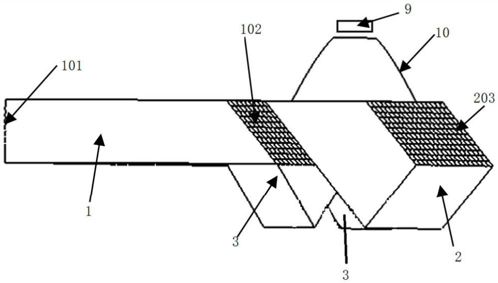
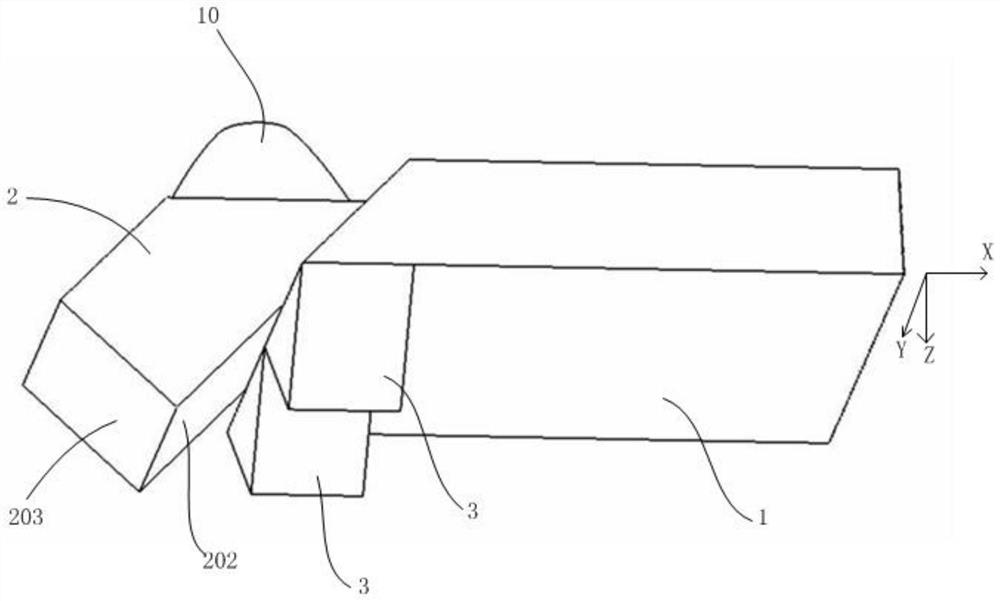
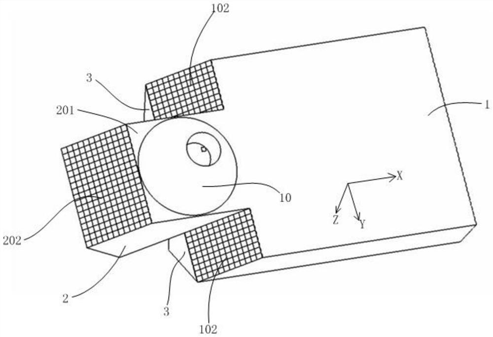
[0034] A thick-walled structure such as Figure 1-Figure 6 As shown, it includes a light guide structure body, the light guide structure body has a light source incident surface 201, a first reflective surface group, a second reflective surface group, and a light exit surface 101 arranged perpendicularly to the light source incident surface 201; the first The reflective surface group is suitable for reflecting the incident light 4 in the plane perpendicular to the light exit surface 101 and the light source incident surface 201, and form...


PUM


Abstract

The invention discloses a thick-wall part structure, a light-emitting device and a light-emitting mode. The thick-wall part structure comprises a light guide structure body, and the light guide structure body is provided with a light source incident plane, a first reflecting plane set, a second reflecting plane set and a light-emitting plane perpendicular to the light source incident plane; the first reflecting plane set is suitable for reflecting incident light in a plane perpendicular to the light-emitting plane and the light source incident plane and forming a central light-emitting area on the light-emitting plane; and the second reflecting plane set diverges the incident light towards two opposite sides parallel to the light-emitting plane, and forms a diffusion light-emitting area on the light-emitting plane, so that the light-emitting width on the light-emitting plane is greater than the width of the light source incident surface. Light emitting of the central area is guaranteed, meanwhile, the diffusion light emitting area is added, the light emitting width is larger than the initial irradiation width of the light sources, when the distance between the light sources is large, the area between the two light sources can be completely irradiated, dark areas are avoided, and the uniform light emitting requirement of customers is met.

Description

technical field [0001] The invention relates to an optical system structure applied to automobile lamps, and belongs to the technical field of automobile lighting. In particular, it relates to a thick-walled part structure, a light emitting device and a light emitting method. Background technique [0002] The mature development of LED light source technology has gradually replaced halogen bulbs as the preferred light source for vehicles. The development of LED light source makes the optical design scheme of LED light source, concentrator and thick-walled parts widely used in the design of car lights. However, with the in-depth research on non-imaging optics, designers and customers have more stringent requirements on the uniformity of non-imaging optics. [0003] The current structure of thick-walled parts can only emit light within the initial irradiation range of the LED light source, that is, the size of the light-emitting area is approximately equal to the size of the ...

Claims


Application Information

Patent Timeline
Patent Type & Authority Applications(China)
IPC IPC(8): F21S41/24F21S41/32F21S43/235F21S43/245F21S43/31F21W102/00F21W103/00F21W107/10F21Y115/10
CPCF21S41/24F21S41/32F21S43/235F21S43/245F21S43/31F21W2102/00F21W2103/00F21W2107/10F21Y2115/10F21S43/40
Inventor 徐岩修蒋毛毛胡文彬张颖
Owner CHANGZHOU XINGYU AUTOMOTIVE LIGHTING SYST CO LTD
Why Eureka
Try Eureka