
Heat exchange tube of falling film evaporator

A falling film evaporator and heat exchange tube technology, which is applied in the field of heat exchange tubes, can solve the problems of adverse effects on heat exchange efficiency of heat exchange tubes, poor setting of T-shaped fins, etc., so as to improve heat exchange efficiency and speed up Flow speed, the effect of improving circulation efficiency

Pending Publication Date: 2022-02-18
QINGDAO HAIER AIR CONDITIONING ELECTRONICS CO LTD +1
View PDF6 Cites 0 Cited by
  • Summary
  • Abstract
  • Description
  • Claims
  • Application Information

AI Technical Summary

Problems solved by technology

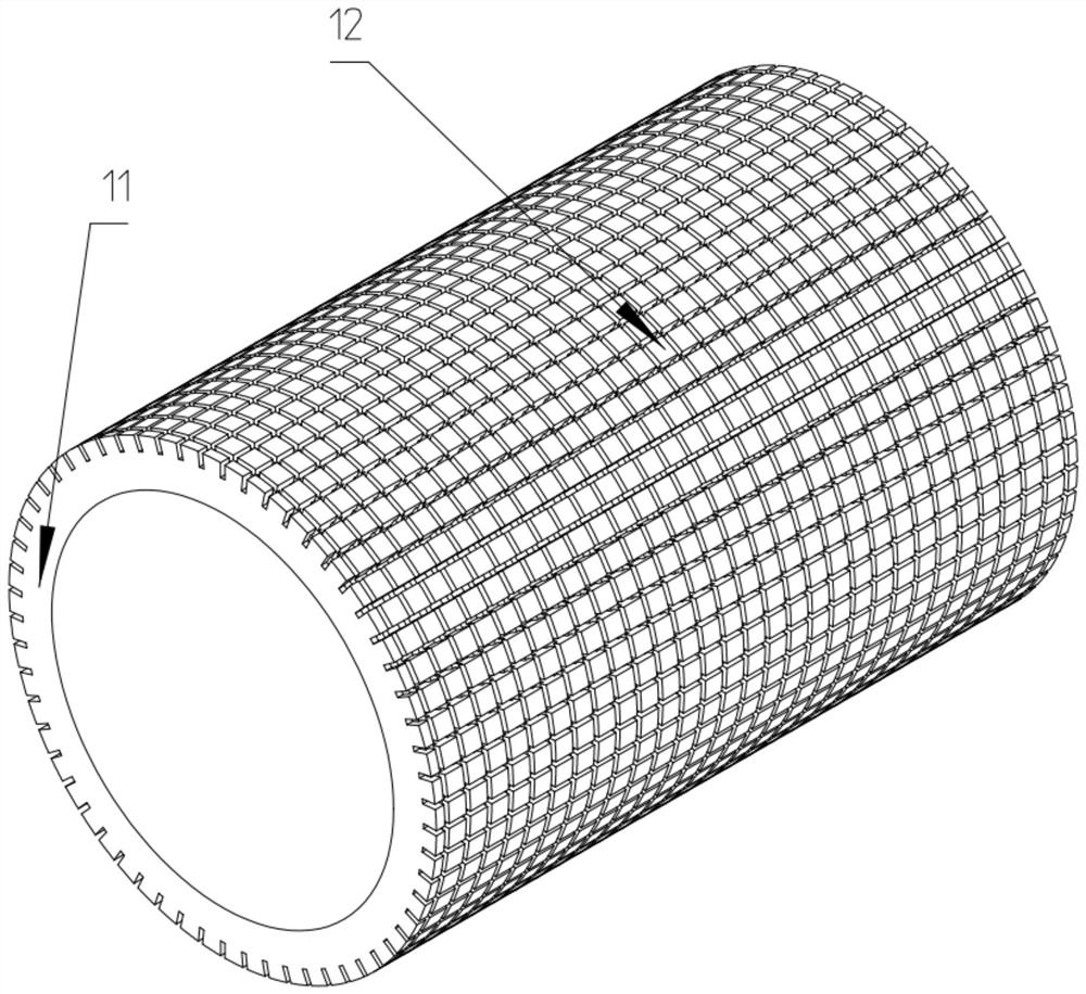
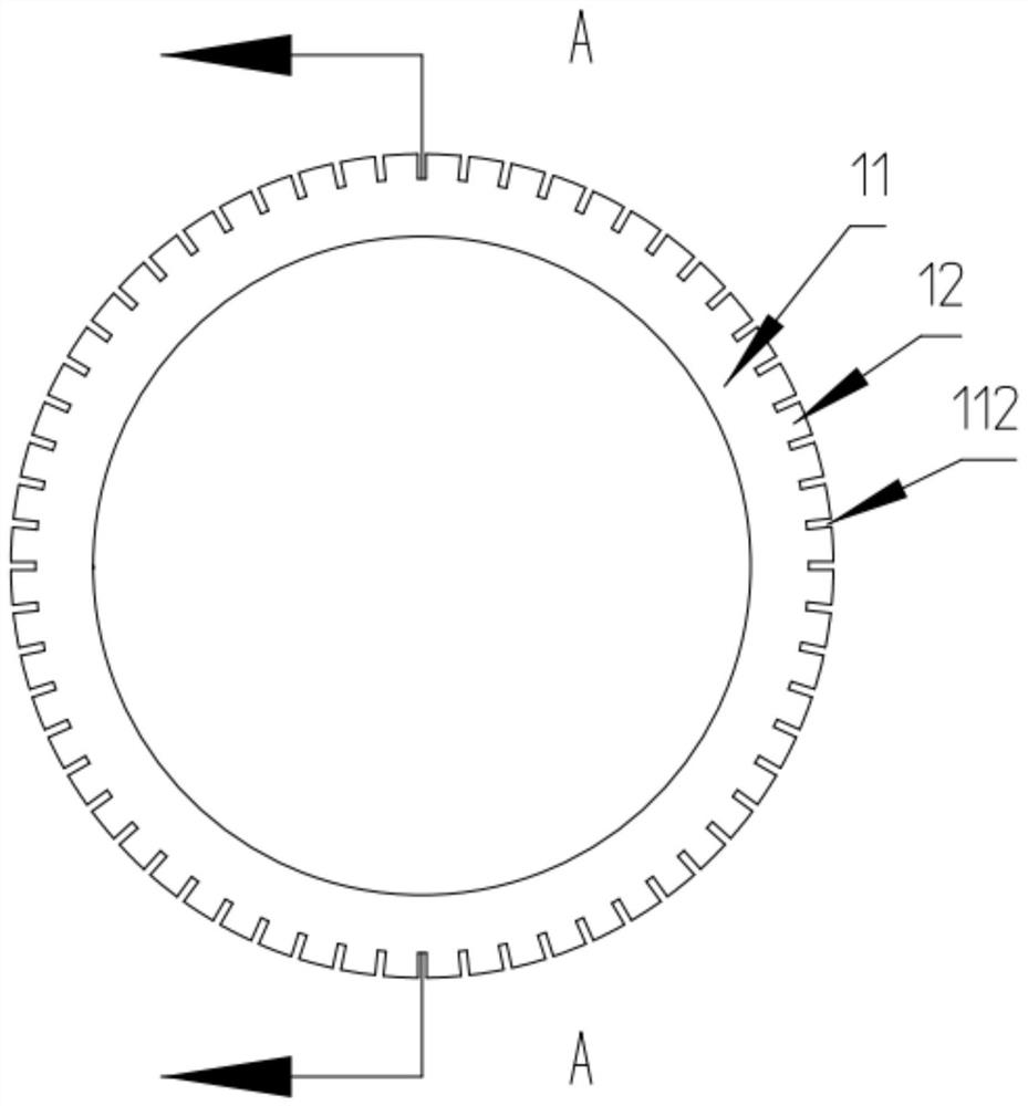
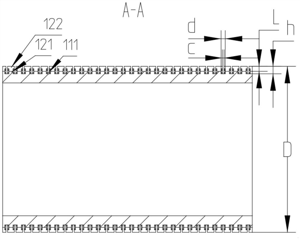
[0005] In order to solve the above-mentioned problems in the prior art, that is, to solve the problem that the heat exchange efficiency of the heat exchange tube is adversely affected by the bad arrangement of the T-shaped fins of the existing heat exchange tube, the present invention provides a A heat exchange tube of a film evaporator, the heat exchange tube includes a tubular main body and a plurality of annular fins arranged on the tubular main body at intervals along the axial direction of the tubular main body, the annular fins The cross-sections are all T-shaped and the vertical part of the annular fins is connected to the tubular main body so that a circumferential liquid guide groove with a T-shaped cross-section is formed between every two adjacent annular fins, The plane where the circumferential liquid guide groove is located is perpendicular to the axis of the tubular body, and the heat exchange tube further includes at least one axial liquid guide that penetrates the plurality of annular fins along the axial direction of the tubular body. grooves so that all the heat transfer fluids of the circumferential liquid guide grooves can flow mutually

Method used


Image

  • Heat exchange tube of falling film evaporator
  • Heat exchange tube of falling film evaporator
  • Heat exchange tube of falling film evaporator

Examples


Embodiment Construction

[0024] Preferred embodiments of the present invention are described below with reference to the accompanying drawings. Those skilled in the art should understand that these embodiments are only used to explain the technical principles of the present invention, and are not intended to limit the protection scope of the present invention. Those skilled in the art can make adjustments as needed so as to adapt to specific applications. For example, it should be noted that in the description of the present invention, the terms "upper", "lower", "left", "right", "vertical", "horizontal", "inner", "outer" and so on indicate The terms of direction or positional relationship are based on the direction or positional relationship shown in the drawings, which are for convenience of description only, and do not indicate or imply that the device or element must have a specific orientation, be constructed and operated in a specific orientation, and therefore It should not be construed as a l...


PUM


Abstract

The invention belongs to the technical field of heat exchange, and particularly provides a heat exchange tube of a falling film evaporator. The invention aims to solve the problem that the arrangement mode of T-shaped fins of an existing heat exchange tube is not good, so that the heat exchange efficiency is easily influenced. Therefore, the heat exchange tube of the falling film evaporator comprises a tubular main body and a plurality of annular fins which are arranged on the tubular main body at intervals in the axial direction of the tubular main body, the sections of the annular fins are all in a T shape, the vertical parts of the annular fins are connected with the tubular main body so that a circumferential liquid guide groove with the T-shaped section can be formed between every two adjacent annular fins, and the plane where the circumferential liquid guide grooves are located is perpendicular to the axis of the tubular main body. The heat exchange tube further comprises at least one axial liquid guide groove penetrating through the multiple annular fins in the axial direction of the tubular main body so that heat exchange working media of all the circumferential liquid guide grooves can flow mutually. It can be effectively guaranteed that the heat exchange working medium forms a uniform and complete liquid film on the outer surface of the heat exchange pipe, and then the heat exchange efficiency of the heat exchange pipe is effectively improved.

Description

technical field [0001] The invention belongs to the technical field of heat exchange, and specifically provides a heat exchange tube of a falling film evaporator. Background technique [0002] As a commonly used evaporator, the falling film evaporator mainly relies on its heat exchange tube to realize the heat exchange process, and the heat exchange mechanism of the heat exchange tube is mainly thin film evaporation heat exchange, forming a liquid film on the outer surface of the heat exchange tube Due to the small thermal resistance, it has high-efficiency heat transfer performance, that is, the heat transfer performance of the liquid film determines the heat transfer performance of the heat exchange tube, so whether the liquid film can evenly cover the outer surface of the heat exchange tube also affects the falling film evaporation. The heat transfer performance of the device plays a decisive role. The formation of the liquid film mainly depends on the flow of the heat e...

Claims


Application Information

Patent Timeline
Patent Type & Authority Applications(China)
IPC IPC(8): F28F1/16F28F1/26
CPCF28F1/16F28F1/26F28F1/12F28F1/18
Inventor 李银银宋强任滔刘江彬
Owner QINGDAO HAIER AIR CONDITIONING ELECTRONICS CO LTD
Learn More