Self-power-generation switch device

A switching device and self-generating technology, applied in electrical switches, electromechanical devices, circuits, etc., can solve the problems that the switch cannot be changed at will, trouble, environmental pollution, etc., and achieve the effect of easy to change the setting position and improve the service life.

Pending Publication Date: 2022-02-18
CHICONY ELECTRONICS
View PDF0 Cites 0 Cited by
  • Summary
  • Abstract
  • Description
  • Claims
  • Application Information

AI Technical Summary

Problems solved by technology

[0003] At present, the common power supply methods for switches are mostly mains or batteries, and the power supply through the mains requires complex wiring, which not only affects the appearance of the environment, but also the position of the switch cannot be changed at will.
By installing a battery for power supply, it needs to be replaced or charged when the battery power is exhausted, causing inconvenience and trouble in use and affecting the service life of the switch. In addition, the replaced battery will also cause environmental pollution.

Method used


Image

  • Self-power-generation switch device
  • Self-power-generation switch device
  • Self-power-generation switch device

Examples


Embodiment Construction

[0051] Various embodiments are proposed below for detailed description. However, the embodiments are only used as examples for illustration and will not limit the scope of protection of the present invention. In addition, some elements are omitted from the description and drawings in the embodiments to clearly show the technical features of the present invention. The same reference numbers will be used throughout the drawings of the specification to refer to the same or similar elements.

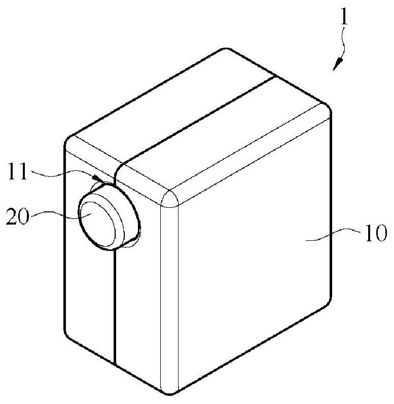
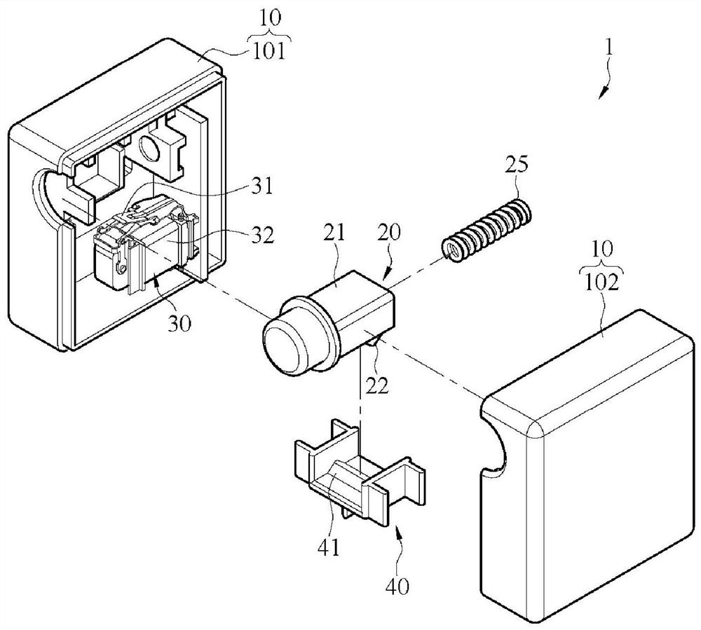
[0052] figure 1 It is a perspective view of the first embodiment of the self-generating switching device 1 of the present invention, figure 2 It is an exploded perspective view of the first embodiment of the self-generating switching device 1 of the present invention. Such as figure 1 and figure 2 As shown, the self-generating switching device 1 includes a housing 10 , a switch 20 , a generating module 30 and a movable seat 40 . Among them, the self-generating switch device 1 can be u...


PUM


Abstract

The invention discloses a self-power-generation switch device which comprises a shell, a switch, a power generation module and a movable seat. The shell comprises an assembling opening. The switch group is arranged at the assembly port and located at an initial position, and the switch can sequentially move to a first trigger position and a second trigger position in the same moving direction relative to the shell. The power generation module is arranged in the shell. The movable seat is movably arranged in the shell and abuts between the power supply generation module and the switch. Wherein the switch generates a first electric signal when moving from an initial position to a first trigger position, and generates a second electric signal when moving from the first trigger position to a second trigger position.

Description

technical field [0001] The present invention relates to a switchgear, in particular to a self-generating switchgear. Background technique [0002] A switch is a common device in a power system, which is used to open a circuit, break a circuit, or pass current to electronic components in other circuits to control the opening and closing or operation of electrical equipment, such as controlling the lights in the home environment or the sound of the doorbell Wait. [0003] At present, the common power supply methods for switches are mostly mains or batteries. The power supply through the mains requires complex wiring, which not only affects the appearance of the environment, but also the position of the switch cannot be changed arbitrarily. If the battery is installed for power supply, it needs to be replaced or charged when the battery power is exhausted, causing inconvenience and trouble in use and affecting the service life of the switch. In addition, the replaced battery w...

Claims


Application Information

Patent Timeline
IPC IPC(8): H01H9/02H02K7/18
CPCH01H9/02H02K7/18
Inventor 陈璟忠
Owner CHICONY ELECTRONICS
Why Eureka
Try Eureka