Movable energy storage container heat dissipation device and movable energy storage container

A cooling device and container technology, applied to electrochemical generators, electrical components, circuits, etc., can solve problems such as low wind speed, unbalanced battery temperature, and unreasonable distribution of air-conditioning air volume, so as to reduce wind resistance, improve overall performance, The effect of uniform heat dissipation

Pending Publication Date: 2022-02-18
XJ POWER CO LTD +2
View PDF4 Cites 0 Cited by
  • Summary
  • Abstract
  • Description
  • Claims
  • Application Information

AI Technical Summary

Problems solved by technology

For a single energy storage unit in the energy storage cabin, the air duct is long and there are many air outlets, and the wind speed at the air outlet of the air duct far from the end of the air conditioner is low, which cannot reasonably distribute the air volume discharged by the air conditioner, resulting in energy storage The temperature of the battery in the cabin is not balanced

Method used


Image

  • Movable energy storage container heat dissipation device and movable energy storage container
  • Movable energy storage container heat dissipation device and movable energy storage container
  • Movable energy storage container heat dissipation device and movable energy storage container

Examples


Embodiment Construction

[0033] In order to make the object, technical solution and advantages of the present invention clearer, the present invention will be further described in detail below in combination with specific embodiments and with reference to the accompanying drawings. It should be understood that these descriptions are exemplary only, and are not intended to limit the scope of the present invention. Also, in the following description, descriptions of well-known structures and techniques are omitted to avoid unnecessarily obscuring the concept of the present invention.

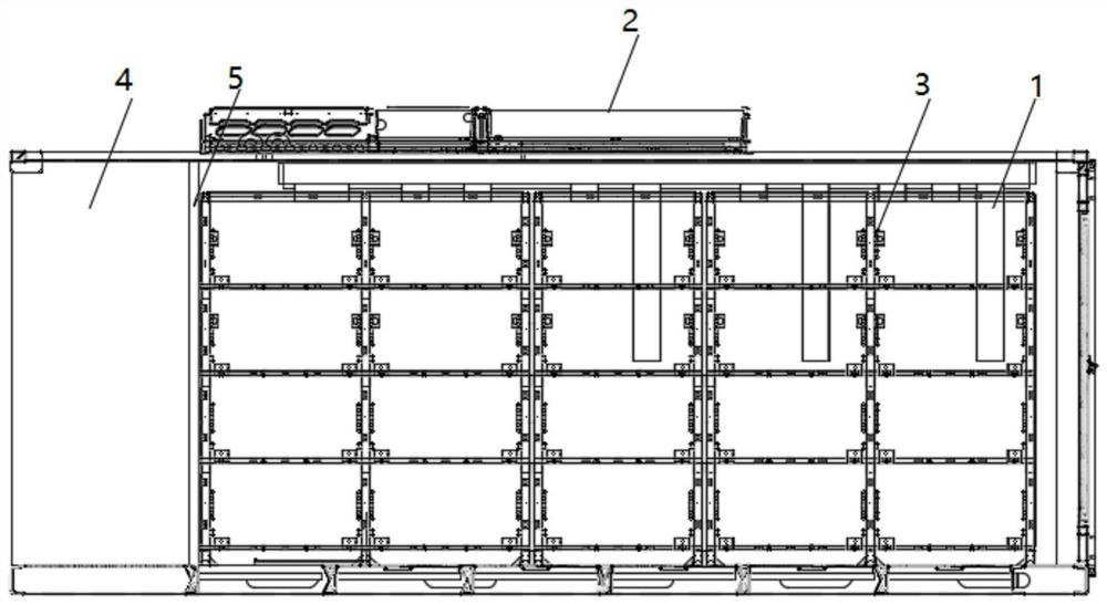
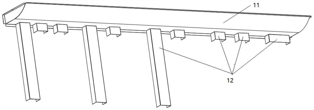
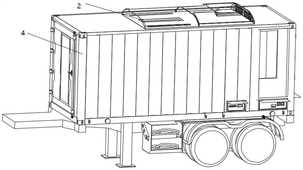
[0034] Please refer to figure 1 , in order to solve the above technical problems, the first aspect of the embodiment of the present invention provides a mobile energy storage container cooling device, the energy storage container 4 is provided with several battery boxes located on the battery rack 3, including: top-mounted The air conditioner 2 and the heat dissipation air duct assembly 1; the top-mounted air conditioner...


PUM


Abstract

The invention discloses a mobile energy storage container heat dissipation device and a mobile energy storage container, a plurality of battery boxes located on a battery rack are arranged in the energy storage container, and the heat dissipation device comprises a top-mounted air conditioner and a heat dissipation air duct assembly; the top-mounted air conditioner is arranged at the top of the energy storage container body, and an air return port of the top-mounted air conditioner is located at the top of the battery rack; the heat dissipation air duct assemblies are arranged on the two sides of the battery rack and fixedly connected with the inner wall of the energy storage container body. An air inlet of the heat dissipation air duct assembly communicates with an air outlet of the top-mounted air conditioner, and a plurality of air outlets of the heat dissipation air duct assembly correspond to the battery boxes in position. The top-mounted air conditioner is arranged at the top of the container, air supply ducts are arranged on the two sides of the battery rack, and the battery boxes at different positions are cooled through the multiple air outlets of the heat dissipation air duct assembly, so that the air resistance of the air ducts is reduced, the air speed of each air outlet is kept consistent, the uniform heat dissipation of the battery boxes at different heights on the battery rack is realized; and the overall performance of the energy storage container is improved.

Description

technical field [0001] The invention relates to the technical field of refrigeration, in particular to a cooling device for a mobile energy storage container and a mobile energy storage container. Background technique [0002] The energy storage cabin is another device that effectively stores and utilizes energy advocated by the state in recent years. It can effectively store electric energy generated by solar energy and wind energy, and provide uninterrupted power supply for grid power failure, emergency rescue power supply, and power shortage areas. At present, the battery energy storage cabin uses containers to store chemical batteries. Chemical batteries are sensitive to temperature changes. Too low temperature will damage the battery, and too high temperature or a short period of time will cause the risk of thermal runaway of the battery. The temperature of the chemical battery is consistent. permanently affect the performance and service life of the entire energy stora...

Claims


Application Information

Patent Timeline
Patent Type & Authority Applications(China)
IPC IPC(8): H01M10/613H01M10/6563H01M10/663H01M50/244
CPCH01M10/613H01M10/6563H01M10/663H01M50/244Y02E60/10
Inventor 甘江华王伟朱传涛高庆勇房相成邵红军任彬红李谦
Owner XJ POWER CO LTD
Why Eureka
Try Eureka