Cooling type transformer
A technology of transformers and casings, applied in the field of cooling transformers, can solve the problems of reduced performance, easy occurrence of high temperature, accumulation of debris, etc., and achieve the effects of improving performance, prolonging service life, and preventing accumulation of debris
- Summary
- Abstract
- Description
- Claims
- Application Information
AI Technical Summary
Problems solved by technology
Method used
Image

Examples
Embodiment example 1
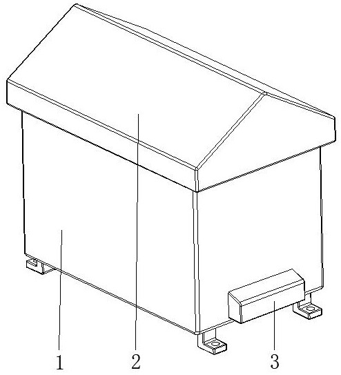
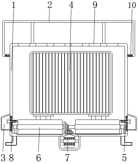
[0031] see Figure 1-Figure 6 , the present invention provides a technical solution: a cooling transformer, including a housing 1, a ceiling 2, and a casing 3, the ceiling 2 is fixed on the top of the casing 1, and the casing 3 is fixed on the corresponding bottom of the surface of the casing 1 both sides;
[0032]The interior of the housing 1 is provided with a transformer main body 4, an air inlet 5, a heat dissipation device 6, a driving mechanism 7, a filter device 8, an air outlet 9, and a filter screen 10, and the transformer main body 4 is arranged at the central position of the housing 1. The air inlet 5 is set at the bottom of the surface of the housing 1 and is located at the position of the casing 3, the heat sink 6 is arranged at the bottom of the inner wall of the housing 1, and the driving mechanism 7 is arranged at the center of the bottom of the inner wall of the housing 1 and is connected to the heat sink 6. The filter device 8 is arranged on the bottom of th...
Embodiment example 2
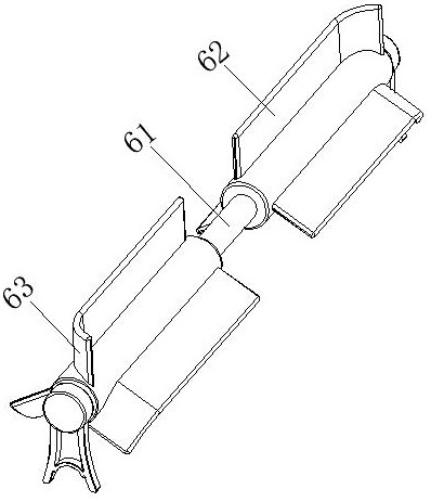
[0034] The cooling device 6 is provided with a rotating shaft 61, a fan blade 62, and an arc-shaped end 63. The end of the rotating shaft 61 is connected with the bottom of the inner wall of the housing 1 through a support seat, and the fan blades 62 are arranged on two corresponding sides of the rotating shaft 61 surface side and close to the end position, the arc-shaped end 63 is arranged on the surface of the fan blade 62 and close to one end of the miscellaneous filter device 8, when the driving mechanism 7 drives the rotating shaft 61 to rotate, the fan blade 62 also rotates accordingly , and then fan the air inside the housing 1, so that the air inside the housing 1 is discharged from the air outlet 9, and the outside air enters the inside of the housing 1 from the air inlet 5, thus forming a cycle, using air convection, The internal heat is dissipated in time, and then the temperature of the transformer main body 4 is rapidly cooled. At the same time, by using the contin...
Embodiment example 3
[0036] The filtering device 8 is provided with a filter baffle 81, a rectangular rubber ring 82, and a press rebound device 83. The filter baffle 81 is connected to the surface bottom of the housing 1 and is positioned at the position of the air inlet 5, and the rectangular rubber ring 82 is fixed on the One side of the surface of the filter baffle 81 is fixedly connected to the housing 1, and the pressing rebound device 83 is arranged at the center of the surface of the filter baffle 81, and the fan blade 62 is used to fan the air in the housing 1, and the air convection , to dissipate the heat in time to cool down, and the filter baffle 81 can block and filter the sundries carried by the air entering the housing 1, and at the same time use the arc-shaped end 63 at the end of the rotating fan blade 62 to press the The pressure generated by the rebound device 83 performs self-cleaning through its own rebound.
PUM
 Abstract
Description
Claims
Application Information
 - R&D
- Intellectual Property
- Life Sciences
- Materials
- Tech Scout
- Unparalleled Data Quality
- Higher Quality Content
- 60% Fewer Hallucinations
Browse by: Latest US Patents, China's latest patents, Technical Efficacy Thesaurus, Application Domain, Technology Topic, Popular Technical Reports.
© 2025 PatSnap. All rights reserved.Legal|Privacy policy|Modern Slavery Act Transparency Statement|Sitemap|About US| Contact US: help@patsnap.com