Antenna and terminal equipment

An antenna and capacitor technology, which is applied in the field of antenna and terminal equipment, can solve the problems of unfavorable machine stacking, low antenna aperture space utilization rate, and large antenna occupation space, so as to save internal space and improve aperture utilization rate.

Pending Publication Date: 2022-02-25
GUANGDONG OPPO MOBILE TELECOMM CORP LTD
View PDF0 Cites 0 Cited by
  • Summary
  • Abstract
  • Description
  • Claims
  • Application Information

AI Technical Summary

Problems solved by technology

However, the antenna aperture space utilization rate is low, and the antenna occupies a large space, which is not conducive to the stacking of the whole machine

Method used


Image

  • Antenna and terminal equipment
  • Antenna and terminal equipment
  • Antenna and terminal equipment

Examples


Embodiment Construction

[0026] The present application provides an antenna and terminal device for increasing the antenna caliber utilization in the premise of the number of antennas, which effectively saves the internal space of the terminal device, which is advantageous for better stacking of the whole machine.

[0027] In order to better understand the present application scheme, the technical solutions in the present application embodiment will be described in connection with the drawings in the present application embodiment, which will be described, and it is intended to be described herein. Embodiments, not all of the embodiments. Based on the embodiments in the present application, it should belong to the scope of this application.

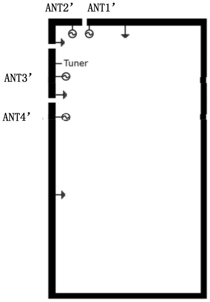
[0028] Below figure 1 The frequency band covered by each antenna shown is illustrated as follows:

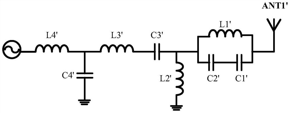
[0029] Ant (Antenna, Antenna) 1 'feeder to the location of the left hand ring, CRLH mode only covers the Global Positioning System (GPS) L5.

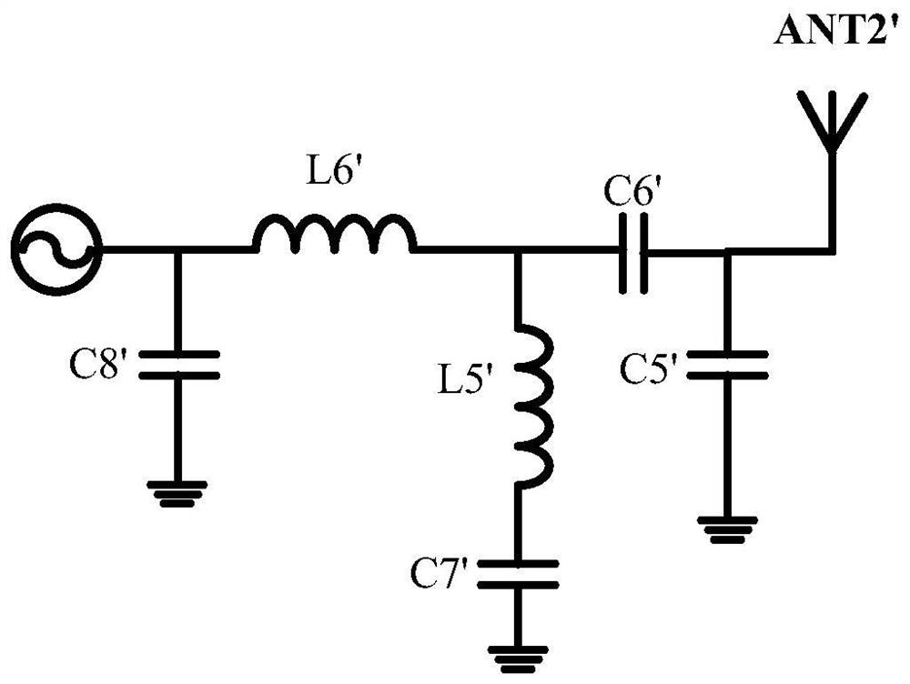
[0030] Ant2 'feeder to t...


PUM


Abstract

The embodiment of the invention discloses an antenna and terminal equipment, which are used for improving the aperture utilization rate of the antennas on the premise that the number of the antennas is not changed, effectively saving the internal space of the terminal equipment and being beneficial to better stacking of a whole machine. The antenna comprises a first antenna, a second antenna, a third antenna and a fourth antenna; the first antenna and the second antenna are in a mouth-to-mouth double-feed design; the first antenna adopts inductance feed, the second antenna adopts capacitance feed, the third antenna adopts capacitance feed, and the fourth antenna adopts capacitance feed or inductance feed.

Description

Technical field [0001] The present application relates to antenna field, in particular to an antenna and a terminal device. Background technique [0002] Existing antenna scheme is a dual-feed feed-by-feed, and the feedback form is a capacitor feed, such as figure 1 As shown, a design schematic of an antenna scheme in the implementation manner. The matching circuit of Ant (Antenna, Antenna) 1 'is to achieve both Ant2' in wireless fidelity, WiFi 2.4G, WiFi5g, and global positioning system (GlobalPositioning System, GPS) L1, it is necessary to achieve itself The impedance tuning of the working frequency band GPS L5, particularly for C1 ', L1', C3 'and other circuits have multiplexed relationships between isolation and tuning. The matching circuit composed of L1 'and C1', C2 'is mainly caused by impedance tuning, and satisfies the segment tuning of WiFi2.4G and WiFi5G. However, the antenna caliber space utilization rate is low, and the antenna is large, which is not conducive to the...

Claims


Application Information

Patent Timeline
Patent Type & Authority Applications(China)
IPC IPC(8): H01Q1/50H01Q1/22H01Q5/20
CPCH01Q1/50H01Q1/22H01Q5/20
Inventor 王生强
Owner GUANGDONG OPPO MOBILE TELECOMM CORP LTD
Why Eureka
Try Eureka