Multimode Composite Antenna

A compound antenna and antenna technology, which is applied in the directions of antenna, antenna coupling, antenna array, etc., can solve the problem of too large antenna array, achieve the effect of simple antenna structure, improve aperture utilization, and solve the effect of too large array

Active Publication Date: 2021-11-23
成都华兴大地科技有限公司
View PDF7 Cites 0 Cited by
  • Summary
  • Abstract
  • Description
  • Claims
  • Application Information

AI Technical Summary

Problems solved by technology

Compared with the traditional single-mode phased array antenna, half of the array is saved, which solves the problem of the two antenna arrays being too large, and is also a direction for the miniaturization of the phased array antenna

Method used


Image

  • Multimode Composite Antenna
  • Multimode Composite Antenna
  • Multimode Composite Antenna

Examples


Embodiment 1

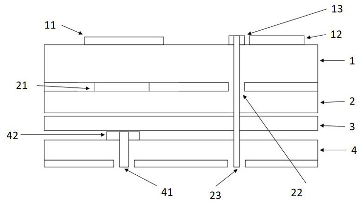
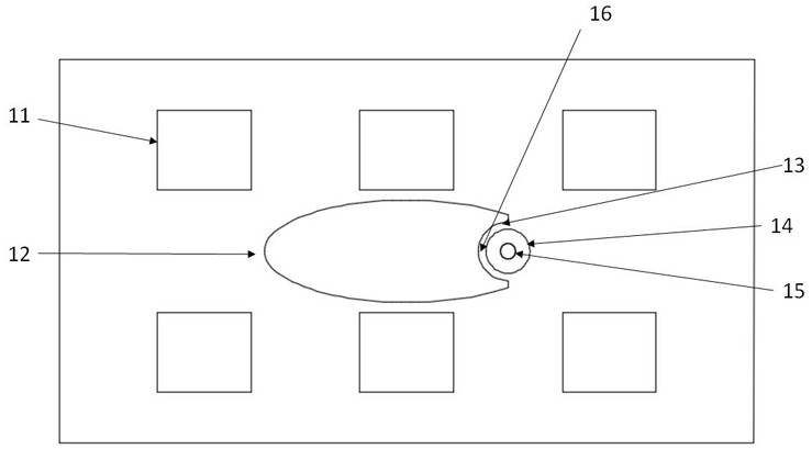
[0044] Such as figure 1 , figure 2 As shown, the multi-mode composite antenna includes an A-band antenna and a B-band antenna,

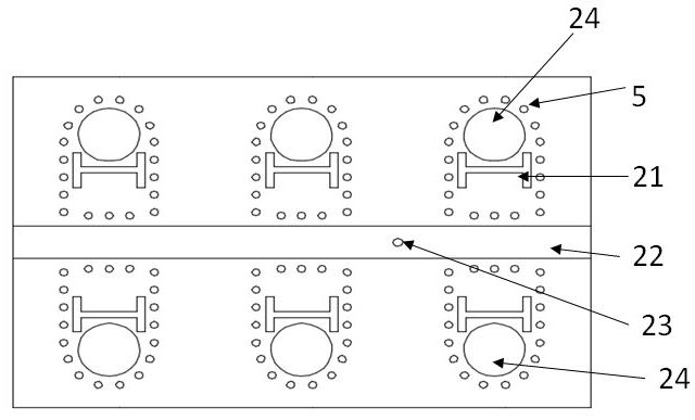
[0045] A-band antenna includes four dielectric layers 1-4, A-band radiation patch 11, heterolayer coupling slot 21, shielding hole 5, feed avoidance slot 22, welding hole 24, shielding hole 5, feeder 42, A-band feed Port 41, A-band feeding ground hole 43;

[0046] The B-band antenna includes four dielectric layers 1-4, the B-band radiation patch 12, the same-layer coupling slot 13, the B-band feed pad 14, the feed hole 15, the feed avoidance slot 22, and the B-band feed port 23;

[0047] One of the polarization types of the two antennas is vertical polarization, and the other is horizontal polarization. By rotating the feeding direction of one of the antennas, the polarization type of its antenna is changed.

[0048] The A-band antenna is a hetero-layer slot-coupling antenna. The radiation patch and the slot are on different layers. The slot-coupli...

Embodiment 2

[0062] Such as Figure 9 As shown, the difference between the present embodiment and the first embodiment is that: the feeding avoidance slot 22 runs through the second dielectric layer 2 longitudinally, and the longitudinal direction is the width direction of the dielectric layer.

[0063] The A-band antenna adopts a different-layer slot coupling antenna. The signal enters the feeder through the insulator, and the slot is coupled to the A-band radiation patch. The B-band antenna uses an insulator to directly feed power to the pad, and is coupled to the B-band radiation patch through the same layer slot. The polarization types of the two antennas are the same linear polarization type. The antenna can be formed into an array antenna. Compared with the traditional phased array antenna, the phased array area is reduced. Compared with Embodiment 1, the difference lies in that the polarization types of the two antennas are the same.

Embodiment 3

[0065] Such as Figure 10 As shown, the difference between this embodiment and Embodiment 1 is that the interlayer coupling gap 21 is in the shape of a spindle. The middle of the spindle body is a horizontal straight segment, and the two ends include two spindle heads.

[0066] In some specific scenarios of high-frequency use, the aperture of the welding hole in the A-band antenna is subject to the processing technology. For the high-frequency antenna, the aperture ratio of the welding hole is relatively large. If the hetero-layer coupling gap 21 of the specific embodiment 1 is used , the hetero-layer coupling gap 21 will interfere with the welding hole. can be used as Figure 10 The spindle-shaped hetero-layer coupling gap 21 shown can solve the problem of interference between the feeding gap and the welding hole during the processing of high-frequency antennas. The A-band antenna adopts a different-layer slot coupling antenna. The signal enters the feeder through the insu...


PUM


Abstract

The present invention provides a multi-mode composite antenna, comprising: four dielectric layers arranged sequentially from top to bottom, the first dielectric layer is provided with multiple groups of periodically arranged units, and each unit is provided with an A-band radiation patch , B-band radiation patches, same-layer coupling gaps, B-band feed pads, and feed holes; the second dielectric layer is provided with welding holes, hetero-layer coupling gaps, feed avoidance gaps, and shielding holes; the third dielectric layer is provided with There are welding holes, shielding holes, and B-band feed ports. The fourth dielectric layer is divided into upper surface copper clad layer and bottom copper clad layer; A-band radiation patch and B-band radiation patch share the same aperture. The polarizations of the two antennas may be the same linear polarization in the same direction, or two types of linear polarization in mutually perpendicular directions. The invention has a simple structure, and can be used not only for regularly arranged phased array antennas, but also for sparsely arranged phased array antennas, which solves the problem of the two antenna arrays being too large, and can simultaneously ensure the scanning performance of antennas in two frequency bands .

Description

technical field [0001] The invention belongs to the technical field of microstrip dual-mode composite phased array antennas, and in particular relates to a common-aperture dual-mode composite microstrip antenna that can be used for phased array antennas. Background technique [0002] With the rapid development of wireless communication technology, communication equipment is developing in the direction of miniaturization and integration. The performance of the antenna determines the performance of the entire system, so the research on the antenna is becoming more and more important, and the dual-mode common-aperture composite antenna is one of the key technologies in the research of the phased array antenna. [0003] After the traditional microstrip antenna units are arrayed, there is only a single mode antenna in the entire antenna aperture, and its aperture utilization rate is relatively low. If two antennas with different frequency bands are used to form an array, two sep...

Claims


Application Information

Patent Timeline
Patent Type & Authority Patents(China)
IPC IPC(8): H01Q1/38H01Q21/00H01Q1/48H01Q1/50H01Q1/52
CPCH01Q1/38H01Q21/00H01Q21/0006H01Q1/50H01Q1/521H01Q1/526H01Q1/48
Inventor 郭丽凤朱伟李力力
Owner 成都华兴大地科技有限公司
Why Eureka
Try Eureka