Network protocol conversion module within telecommunications system

A technology of communication network and conversion module, which is applied in the field of conversion of application layer signals, and can solve problems such as not including

Inactive Publication Date: 2004-03-03
TELEFON AB LM ERICSSON (PUBL)
View PDF0 Cites 0 Cited by
  • Summary
  • Abstract
  • Description
  • Claims
  • Application Information

AI Technical Summary

Problems solved by technology

However, this document does not cover systems for communicatin

Method used


Image

  • Network protocol conversion module within telecommunications system
  • Network protocol conversion module within telecommunications system
  • Network protocol conversion module within telecommunications system

Examples


Embodiment Construction

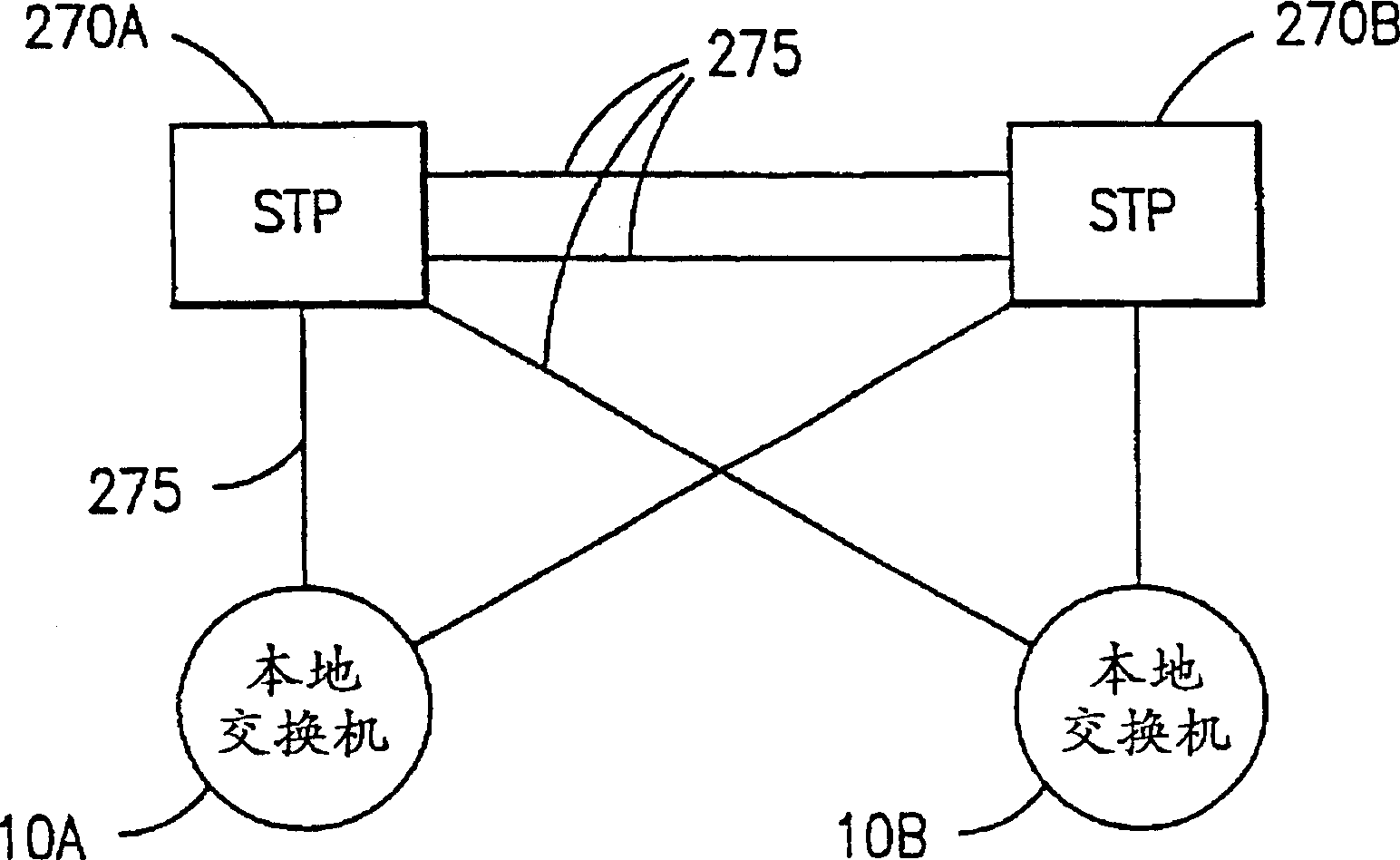
[0037] figure 1is a diagram representing a portion of a typical SS7 communication network in which the invention disclosed herein may be implemented. With the development of digital switches, Common Channel Signaling (CCS) has rapidly become the best way to handle call continuation in circuit-switched networks. The most commonly used technique for implementing CCS in the United States has been Signaling System No. 7, first created by the Consultative Committee for International Telegraph and Telephone (CCITT) and later modified by the American National Standards Institute (AMSI). In order to perform routing and signaling functions within the network, messages must be sent from local switch A 10A to local switch B 10B via a packet-switched signaling network. Dual signal transfer points (STPs) 270A and 270B are designed to provide reliable transfer of signaling messages by providing always more than one signal link 275 link between any two nodes. These signals containing appli...


PUM


Abstract

Signaling Connection Control Part (SCCP) parameters within a signal generated within a first SS7 telecommunications network are converted into values and formats acceptable by a second SS7 telecommunications network by a converter residing within a gateway Signal Transfer Point (STP). Such a converter enables signals containing application layer data to be transported across two different SS7 telecommunications networks that are otherwise incompatible.

Description

technical field [0001] The present invention relates to the communication of application layer signals across different telecommunication networks, and more particularly to the conversion of application layer signals between a first Signaling System No. 7 (SS7) telecommunication network and a second SS7 telecommunication network, wherein the first and second Two SS7 communication networks are not compatible. Background technique [0002] A typical telecommunications switch is a complex digital processor containing a large number of devices, signaling terminals and most importantly, software and hardware modules that provide communication services to communication users. With the aforementioned development of digital processors and Common Channel Signaling (CCS) networking systems, typical telecommunications switches are now capable of supporting and transmitting much more than just voice data. Such data may include video images, control signals, or application specific info...

Claims


Application Information

Patent Timeline
IPC IPC(8): H04M7/06H04L29/06H04Q3/00
CPCH04L69/08H04Q3/0025
Inventor J·林德奎斯特C·M·菲尔特纳
Owner TELEFON AB LM ERICSSON (PUBL)
Why Eureka
Try Eureka