
Mould capable of being quickly demoulded

A mold and demolding technology, applied in the field of molds that can be quickly demolded, can solve the problems of discontinuous processing, inconvenient demoulding, and low efficiency, and achieve the effect of maintaining processing continuity

Pending Publication Date: 2022-03-01
SUZHOU QINDE METAL
View PDF0 Cites 0 Cited by
  • Summary
  • Abstract
  • Description
  • Claims
  • Application Information

AI Technical Summary

Problems solved by technology

[0003] The purpose of the present invention is to provide a mold that can be quickly demolded to solve the problem that the punching and stamping of the copper connectors of charging piles proposed in the above background technology are carried out on independent equipment, and the processing is discontinuous and the efficiency is low. , most of them are loaded and unloaded manually, which is inconvenient when demoulding, and there are certain safety hazards when loading and unloading manually

Method used


Image

  • Mould capable of being quickly demoulded
  • Mould capable of being quickly demoulded
  • Mould capable of being quickly demoulded

Examples


Embodiment Construction

[0035] The following will clearly and completely describe the technical solutions in the embodiments of the present invention with reference to the accompanying drawings in the embodiments of the present invention. Obviously, the described embodiments are only some, not all, embodiments of the present invention. Based on the embodiments of the present invention, all other embodiments obtained by persons of ordinary skill in the art without making creative efforts belong to the protection scope of the present invention.

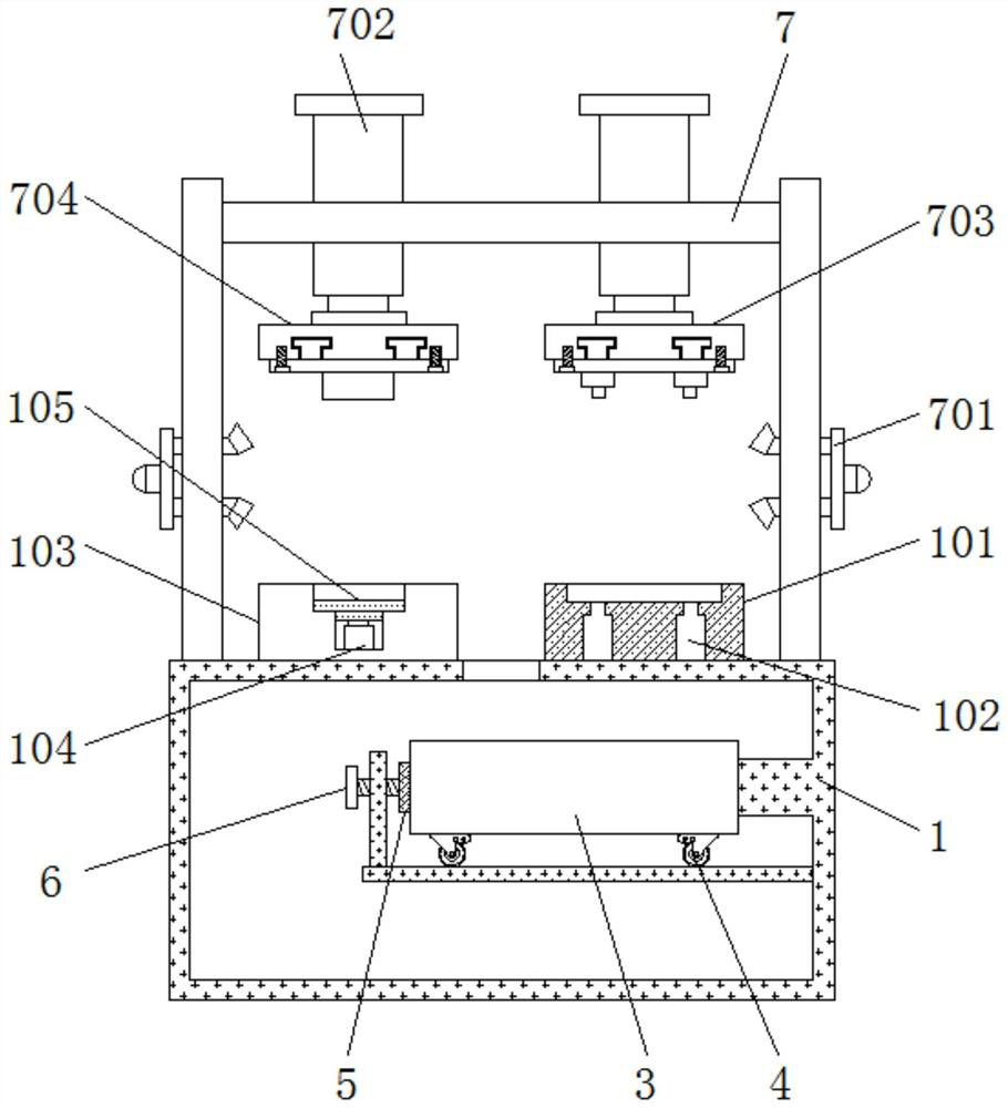
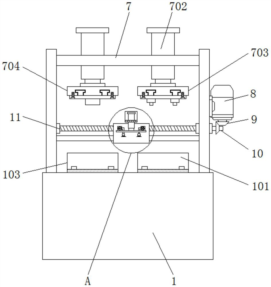
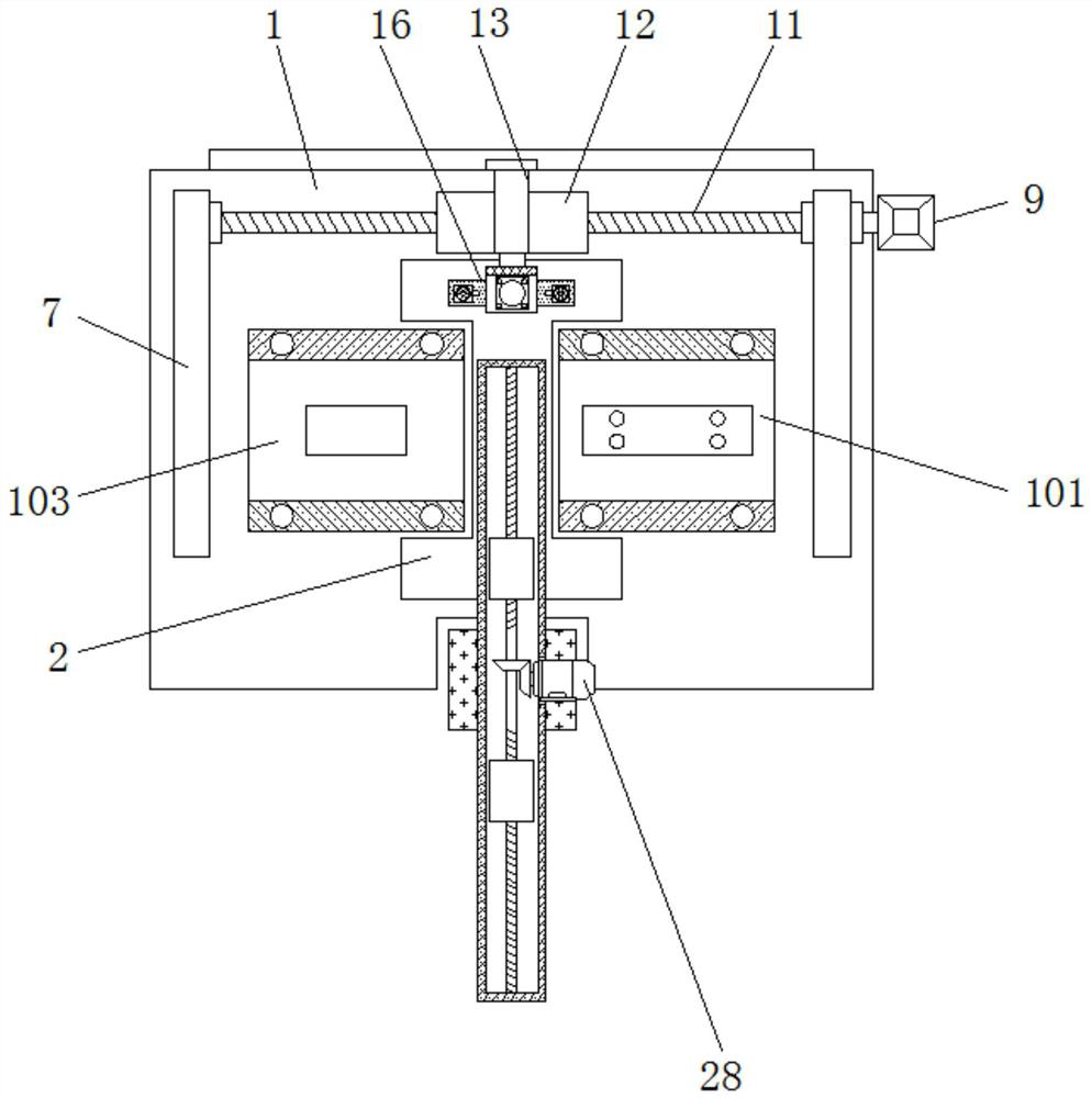
[0036] see Figure 1-6 , the present invention provides a technical solution: a mold that can be released quickly, such as figure 1 , figure 2 and image 3 As shown, the upper end of the device frame 1 is provided with an opening groove 2, and the upper end of the device frame 1 is provided with a processing frame 7. The device frame 1 includes a first lower mold 101, a blanking hole 102, a second lower mold 103, and an electric telescopic rod. 104 and a t...


PUM


Abstract

The mold comprises a device frame, a collecting box, a first motor, a fixing frame and a second lead screw, a through opening groove is formed in the upper end of the device frame, a machining frame is arranged at the upper end of the device frame, the fixing frame is arranged on the front side of the device frame, a second motor is arranged in the fixing frame, and the second motor is connected with a transmission shaft. According to the mold capable of rapidly demolding, a second vacuum chuck is pushed to adsorb an original copper connecting piece under the action of a third hydraulic telescopic rod on the front side, a transfer frame is driven to rotate through a transmission shaft under the action of a second motor, and the original copper connecting piece is placed in a first lower mold and punched through a first upper mold; a punched copper connecting piece is adsorbed under the action of a first hydraulic telescopic rod, a supporting frame, a second hydraulic telescopic rod and a first vacuum suction cup mechanism, a first lead screw is driven to rotate through a first motor, a first bevel gear set and a rotating shaft, the punched copper connecting piece is transferred to be subjected to punch forming machining, and machining continuity is kept.

Description

technical field [0001] The invention relates to the related technical field of charging pile processing, in particular to a mold that can be quickly demolded. Background technique [0002] In the production and processing process of the copper connector of the charging pile, the copper sheet needs to be punched and stamped through the stamping die. Generally, the punching and stamping of the copper connector of the charging pile are carried out on independent equipment, and the workpiece needs to be processed. Transfer processing, processing is discontinuous, and the efficiency is low. At the same time, when the existing copper connectors of charging piles are processed through stamping dies, most of them are manually loaded and unloaded. Hidden danger. Contents of the invention [0003] The purpose of the present invention is to provide a mold that can be quickly demolded to solve the problem that the punching and stamping of the copper connectors of charging piles propo...

Claims


Application Information

Patent Timeline
Patent Type & Authority Applications(China)
IPC IPC(8): B21D35/00B21D43/20B21D43/18B21D45/02B21D45/04
CPCB21D35/001B21D35/002B21D43/20B21D43/18B21D45/003B21D45/02B21D45/04
Inventor 苏春洲
Owner SUZHOU QINDE METAL
Learn More