Supercharge Your Innovation With Domain-Expert AI Agents!

Machining method for clamping groove of spoke and spoke

A processing method and technology of slots, which are applied in the processing method of slots and the field of spokes, can solve the problems of difficulty in processing slots, etc.

Active Publication Date: 2022-03-01
ZHEJIANG JINGU CO LTD
View PDF5 Cites 0 Cited by
  • Summary
  • Abstract
  • Description
  • Claims
  • Application Information

AI Technical Summary

Problems solved by technology

[0003] The main purpose of the present invention is to provide a method for processing the slots of the spokes and the spokes, so as to solve the problem in the prior art that the slots on the spokes of the wheels are processed by turning, which makes the processing of the slots difficult.

Method used


Image

  • Machining method for clamping groove of spoke and spoke
  • Machining method for clamping groove of spoke and spoke
  • Machining method for clamping groove of spoke and spoke

Examples


Embodiment 1

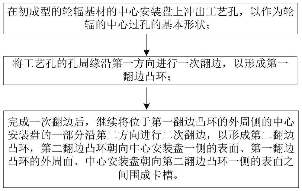
[0035] Such as Figure 1 to Figure 4 As shown, the processing method of the card slot of the spoke, the card slot 1 is used to clamp the decorative cover, including punching out the process hole 12 on the center mounting plate 11 of the initially formed wheel spoke base material 10, as the central via hole of the wheel spoke Basic shape; the hole periphery of the process hole 12 is flanged once along the first direction to form the first flanging convex ring 13; A part of the mounting disc 11 is subjected to secondary flanging along the second direction to form a second flanging protruding ring 14, the surface of the second flanging protruding ring 14 facing the central mounting disc 11 side, the surface of the first flanging protruding ring 13 A slot 1 is formed between the outer peripheral surface and the surface of the central mounting plate 11 facing the second flanged ring 14 .

[0036] It should be noted that, compared with the existing groove 1 formed by turning, the p...

Embodiment 2

[0042] Such as Figure 5 to Figure 11 As shown, the processing method of the slot of the spoke, the slot 1 is used to clamp the decorative cover, including punching out the process hole 12 on the initially formed spoke base material 10, as the basic shape of the central via hole of the spoke; Press the card groove 1 on the first surface of the hole periphery of the hole 12; heat the preset time T at the position where the hole periphery of the process hole 12 has the card groove 1 by the heating device 2; the hole periphery of the process hole 12 after heating Flanging is performed along the axial direction of the process hole 12 so that the card slot 1 is located on the outer peripheral side of the process hole 12 .

[0043] It should be noted that, compared with the existing groove 1 formed by turning, the processing method of the above-mentioned groove of the spoke is much less difficult to process, and can also avoid cracking at the flange as much as possible.

[0044] Su...


PUM


Abstract

The invention provides a machining method of a clamping groove of a spoke and the spoke, the clamping groove is used for clamping a decorative cover, and the machining method comprises the steps that a process hole is punched in a center mounting disc of a pre-formed spoke base material to serve as the basic shape of a center via hole of the spoke; the hole periphery of the process hole is subjected to primary flanging in the first direction, so that a first flanging convex ring is formed; after primary flanging is completed, part, located on the peripheral side of the first flanging convex ring, of the center mounting disc is subjected to secondary flanging in the second direction, so that a second flanging convex ring is formed; a clamping groove is defined by the surface, facing the side of the center installation disc, of the second flanging protruding ring, the peripheral face of the first flanging protruding ring and the surface, facing the side of the second flanging protruding ring, of the center installation disc. The problem that in the prior art, a clamping groove in a spoke of a wheel is machined through turning, and consequently the machining difficulty of the clamping groove is large is solved.

Description

technical field [0001] The present invention relates to the technical field of processing and manufacturing of wheel spokes, in particular to a method for processing wheel spoke slots and the wheel spokes. Background technique [0002] In the prior art, the spokes of the wheel have a central through hole through which the wheel is connected to the axle. In order to avoid dust accumulation at the connection between the central through hole and the axle, a decorative cover is usually clamped at the central through hole of the spoke to play a role. Therefore, the central through hole of the spoke needs to have a slot for clamping and matching with the decorative cover. However, the existing slot is processed by turning, which is difficult to process. Contents of the invention [0003] The main purpose of the present invention is to provide a method for processing the grooves of the spokes and the spokes, so as to solve the problem in the prior art that the grooves on the spok...

Claims


Application Information

Patent Timeline
IPC IPC(8): B23P15/00B60B3/00
CPCB23P15/00B60B3/00Y02T10/86
Inventor 叶燕飞郝彬黄晓枫陈凯
Owner ZHEJIANG JINGU CO LTD
Features
  • R&D
  • Intellectual Property
  • Life Sciences
  • Materials
  • Tech Scout
  • Unparalleled Data Quality
  • Higher Quality Content
  • 60% Fewer Hallucinations
Learn More