Inspection robot camera lifting platform and cable trench inspection robot

A technology of inspection robots and cameras, which is applied in the installation of cables, cable installation devices, TVs, etc., can solve problems such as difficulty in adapting to the cable trench environment, poor temperature change monitoring effect, large installation space and action space, etc., to achieve Large range of motion, ensuring monitoring effect, and reducing assembly volume

Pending Publication Date: 2022-03-01
ELECTRIC POWER RES INST OF STATE GRID ANHUI ELECTRIC POWER +2
View PDF4 Cites 0 Cited by
  • Summary
  • Abstract
  • Description
  • Claims
  • Application Information

AI Technical Summary

Problems solved by technology

However, the disadvantages of the thermal wires are: firstly, the cables located on both sides of the cable trench are arranged in bundles, and the thermal wires can only monitor the high temperature changes of the adjacent cables that are close to each other. The temperature change monitoring effect of the cable at the end is very poor
The cable trench inspection robot disclosed in this patent can operate through the wall through the cable trench, thereby avoiding many usage problems caused by the existence of the firewall, and then can complete the scheduled inspection tasks efficiently; its linear displacement components directly drive One of the force arms imitating the four-bar linkage assembly can also realize the controllable function of the camera's lifting height, but it will require a large installation space and movement space, and it is difficult to adapt to the narrow and cramped cable trench environment

Method used


Image

  • Inspection robot camera lifting platform and cable trench inspection robot
  • Inspection robot camera lifting platform and cable trench inspection robot
  • Inspection robot camera lifting platform and cable trench inspection robot

Examples


Embodiment Construction

[0043] In order to make the purpose, technical solutions and advantages of the embodiments of the present invention clearer, the technical solutions in the embodiments of the present invention will be clearly and completely described below in conjunction with the embodiments of the present invention. Obviously, the described embodiments are part of the present invention Examples, not all examples. Based on the embodiments of the present invention, all other embodiments obtained by persons of ordinary skill in the art without creative efforts fall within the protection scope of the present invention.

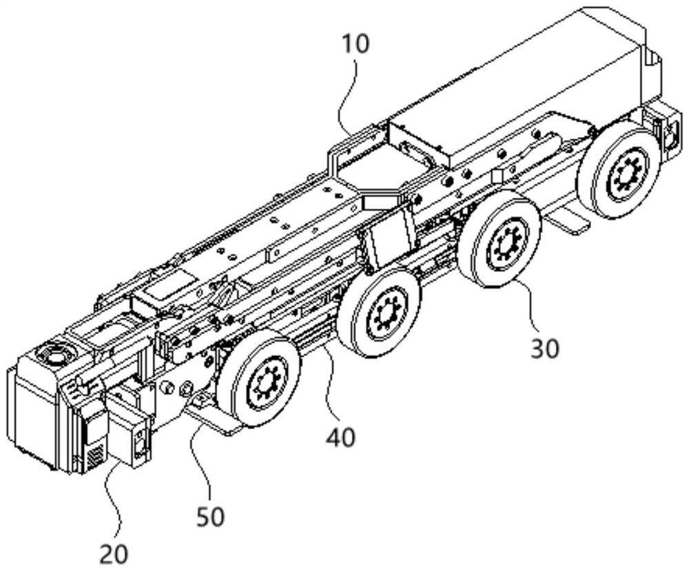
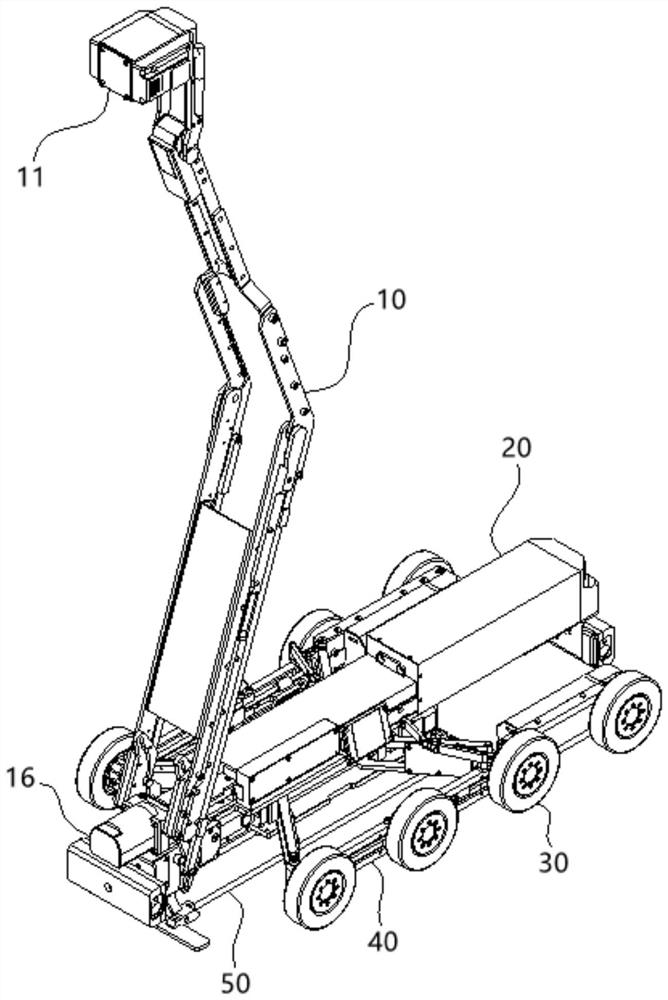
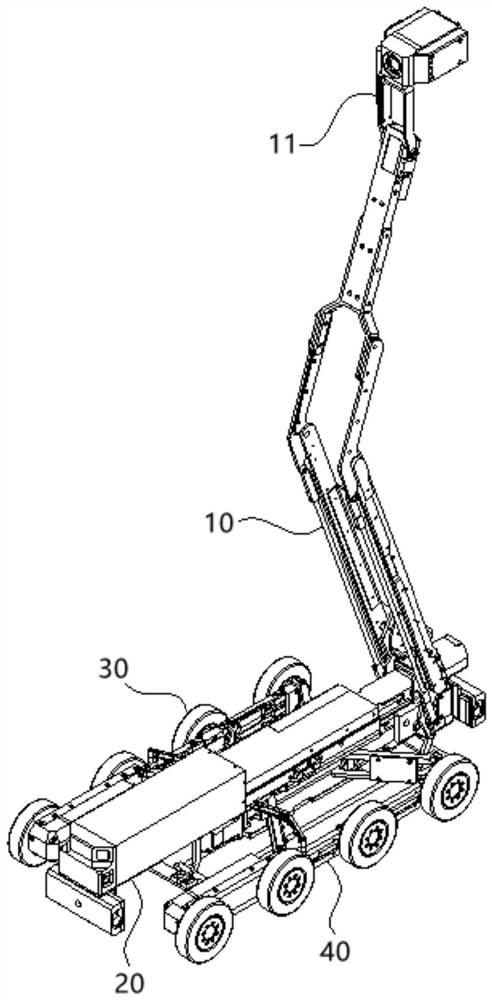
[0044] Such as Figure 1 to Figure 13 As shown, the cable trench inspection robot includes a car body 20, a walking part 30, an unfolding system 40, a jacking system 50, and an inspection robot camera lifting platform 10 installed on the car body 20 as a functional part; the unfolding system 40 is installed on On the vehicle body 20 , two sets of running parts 30 are respectivel...


PUM


Abstract

The invention discloses an inspection robot camera lifting platform and a cable trench inspection robot, and relates to the technical field of cable inspection, and the inspection robot camera lifting platform comprises a working unit, a four-bar linkage assembly and a straight stroke driving mechanism; the working unit comprises a camera and a pitching mechanism, and the pitching mechanism can drive the camera to generate pitching action; the four-connecting-rod assembly comprises an upper long connecting rod, a lower long connecting rod, a head-end short connecting rod and a tail-end short connecting rod, and the head-end short connecting rod, the upper long connecting rod, the tail-end short connecting rod and the lower long connecting rod are sequentially hinged through a horizontal shaft; the straight-stroke driving mechanism comprises a straight-stroke driving source, the four-connecting-rod assembly is hinged to the straight-stroke driving source through a hinged shaft of a head-end short connecting rod and an upper-portion long connecting rod, and the working end of the straight-stroke driving source is in sliding fit with the upper-portion long connecting rod and the head-end short connecting rod. The cable trench has the advantage of being capable of better adapting to the narrow and cramped cable trench environment.

Description

technical field [0001] The invention relates to the technical field of cable inspection, in particular to an inspection robot camera lifting platform and a cable trench inspection robot. Background technique [0002] The occurrence of cable trench fire is a gradual accumulation process. With the increase of time, due to the aging of the insulation layer, the accumulation of dust and oil, and the looseness of the intermediate joints, the local temperature of the cable will gradually rise, which will cause a fire. Before the accident, if the temperature and smoke inside the cable trench can be effectively monitored in real time, the fire can be prevented before it happens. Although the monitoring problem of the cable trench has attracted people's attention, a proper and reasonable solution has not been found. Traditional cable trench inspections use manual inspections. At regular intervals, inspectors enter the tunnel and use temperature measuring instruments to manually ch...

Claims


Application Information

Patent Timeline
Patent Type & Authority Applications(China)
IPC IPC(8): B25J11/00G07C1/20H02G1/00H04N5/225
CPCB25J11/00H02G1/00G07C1/20H04N23/50
Inventor 孙韬张佳庆严波柯艳国谢佳谢铖叶良鹏范明豪甄超操松元樊培培章彬彬尚峰举过羿黄玉彪吴永恒刘睿程宜风祝现礼
Owner ELECTRIC POWER RES INST OF STATE GRID ANHUI ELECTRIC POWER
Why Eureka
Try Eureka