Automatic sampling structure for pipe production

An automatic sampling and pipe technology, applied in the direction of automatic packaging control, packaging, packaging protection, etc., can solve the problems of large inspection workload, low sampling efficiency, low sampling efficiency, etc., to reduce workload, facilitate packaging, compact effect

Pending Publication Date: 2022-03-01
ERA PIPELINE (CHONGQING) CO LTD
View PDF10 Cites 0 Cited by
  • Summary
  • Abstract
  • Description
  • Claims
  • Application Information

AI Technical Summary

Problems solved by technology

During the production of pipes, in order to improve the transportation efficiency of the pipes, the pipes are usually transported by the transmission structure. When sampling, the pipes to be drawn need to be manually removed from the transmission structure, and then tested, which leads to the inspection personnel. Always be next to the transmission structure, which makes the detection workload larger and the sampling efficiency lower
In order to avoid defective products being packaged and sold, pipes can only be packaged and transported to the warehouse after sampling and testing pass. Low sampling efficiency will undoubtedly reduce the packaging efficiency of pipes, thereby reducing the output of pipes

Method used


Image

  • Automatic sampling structure for pipe production
  • Automatic sampling structure for pipe production
  • Automatic sampling structure for pipe production

Examples


Embodiment

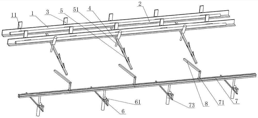
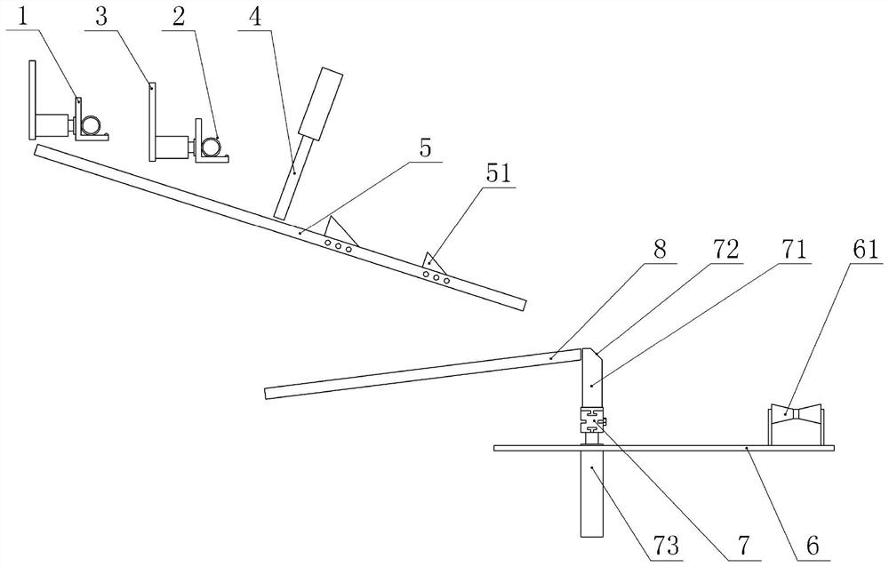
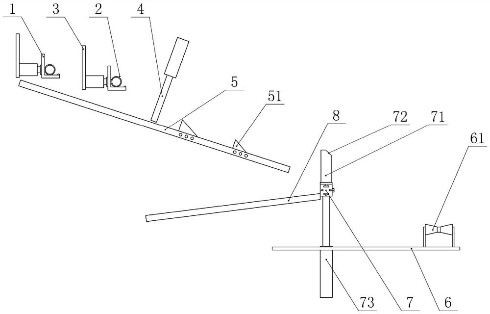
[0029] Automatic sampling structures for pipe production, such as figure 1 As shown, it includes a frame (not shown in the figure), a guide unit and a sampling unit, and the guide unit includes a first guide member 5, an upper push plate, an upper push member, a limit rod 4, a limit member, a first L-shaped Plate, the second L-shaped plate 1 and two baffle plates 51, the first L-shaped plate and the second L-shaped plate 1 are all installed on the frame by bolts, and the second L-shaped plate 1 is located behind the first L-shaped plate side, such as figure 2 As shown, the longitudinal section of the first L-shaped plate and the second L-shaped plate 1 is L-shaped, and the right ends of the first L-shaped plate and the second L-shaped plate 1 are integrally formed with protrusions to prevent the pipeline from moving from the first L-shaped plate. plate and the second L-shaped plate 1 falls.

[0030] Another example figure 1 As shown, the vertical parts of the first L-shape...


PUM


Abstract

The invention relates to the technical field of pipe production, in particular to an automatic sampling structure for pipe production. Comprising a push rod, a guide unit and a sampling unit, the push rod is used for pushing down a pipe from a conveying structure, the guide unit comprises a first guide part, a baffle, an upper push plate and an upper push part, the baffle is installed on the first guide part, the upper push plate is located on the side, close to the push rod, of the baffle, and the upper push part is connected with the upper push plate; the sampling unit comprises a sampling plate and a power piece, a passing gap is formed between the sampling plate and one end, away from the push rod, of the first guide piece, the width of the gap is larger than or equal to the outer diameter of the pipe, and the power piece is connected with the sampling plate. According to the automatic sampling structure for pipe production, the workload can be reduced, the packaging efficiency is improved, and the yield of pipes is increased.

Description

technical field [0001] The invention relates to the technical field of pipe production, in particular to an automatic sampling structure for pipe production. Background technique [0002] Pipes are usually used for the transportation of fluids such as gas and liquid. In order to avoid fluid leakage during use, the pipes need to be sampled and tested after production. During the production of pipes, in order to improve the transportation efficiency of the pipes, the pipes are usually transported by the transmission structure. When sampling, the pipes to be drawn need to be manually removed from the transmission structure, and then tested, which leads to the inspection personnel. Being next to the transmission structure at all times makes the detection workload larger and the sampling efficiency lower. In order to prevent defective products from being packaged and sold, pipes can only be packaged and transported to the warehouse after sampling and testing pass. Low sampling e...

Claims


Application Information

Patent Timeline
Patent Type & Authority Applications(China)
IPC IPC(8): B65B57/14B65B35/22B65B35/10
CPCB65B57/14B65B35/10B65B35/22
Inventor 陈奎林向大军徐建华
Owner ERA PIPELINE (CHONGQING) CO LTD
Why Eureka
Try Eureka