
Novel screw feeding mechanism

A screw and a new type of technology, applied in conveyors, conveyor objects, conveyor control devices, etc., can solve problems such as inability to meet actual needs, reduce labor costs and time costs, and improve production efficiency.

Pending Publication Date: 2022-03-01
JIANGSU COLLEGE OF INFORMATION TECH
View PDF0 Cites 1 Cited by
  • Summary
  • Abstract
  • Description
  • Claims
  • Application Information

AI Technical Summary

Problems solved by technology

[0002] When using screws to fix equipment, the traditional screw placement method is a manual placement method, but in automated production, this method can no longer meet the actual needs. How to efficiently and quickly unload screws is related to the production efficiency of the enterprise. The present invention is based on Based on the structural characteristics of screws, a new type of screw feeding mechanism is proposed

Method used


Image

  • Novel screw feeding mechanism
  • Novel screw feeding mechanism
  • Novel screw feeding mechanism

Examples


Embodiment Construction

[0020] The present invention will be described in further detail below in conjunction with the accompanying drawings.

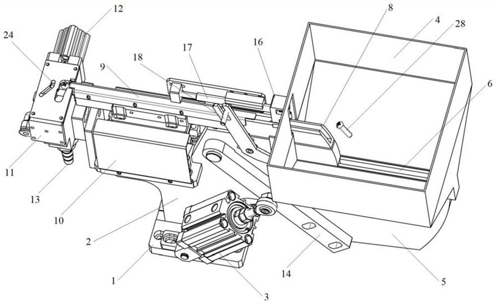
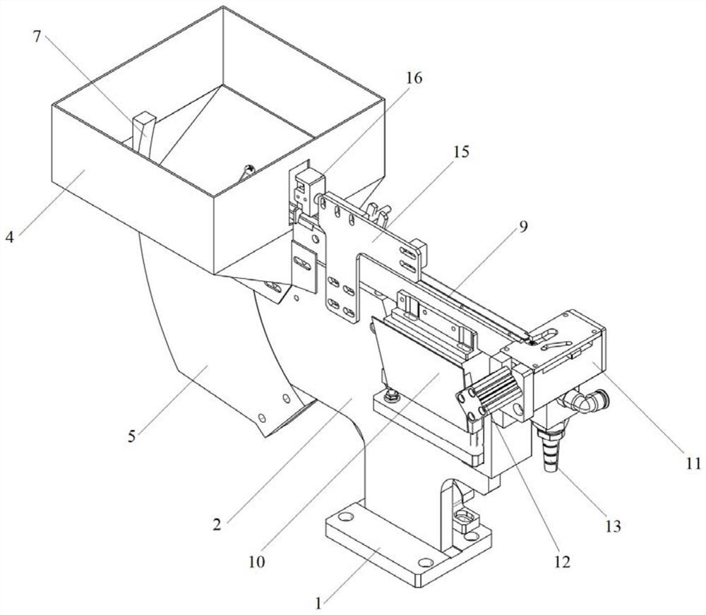
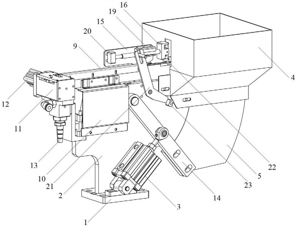
[0021] see Figure 1 to Figure 6 , The screw feeding mechanism provided by the present invention includes a feeding unit, a conveying unit, a feeding unit and an auxiliary mechanism.

[0022] The auxiliary mechanism includes a base 1 and a support plate 2, the support plate 2 is fixed on the base 1, the unloading unit is fixed on the front end of the support plate 2, the feeding unit is fixed on the rear end of the support plate 2, and the conveying unit is fixed on the support plate 2 top.

[0023] In the present invention, the front and rear directions are defined by the movement direction of the screw, that is, the forward direction of the screw is the front.

[0024] The feeding unit includes a feeding cylinder 3 , a square hopper 4 , an arc feeding mechanism 5 and a feeding bracket 14 . The bottom of the feeding cylinder 3 is hinged on the base 1, the...


PUM


Abstract

The novel screw feeding mechanism comprises a feeding unit, a conveying unit, a discharging unit and an auxiliary mechanism, the auxiliary mechanism comprises a base and a supporting plate, the feeding unit comprises a feeding air cylinder, a square hopper, an arc feeding mechanism and a feeding support, and the conveying unit comprises a linear sliding way and a linear feeder. The discharging unit comprises a discharging block and a discharging air cylinder. After entering the square hopper, the screws naturally fall on the hopper groove, the feeding air cylinder is connected with the arc-shaped feeding mechanism through the feeding support, the air cylinder stretches out to drive the arc-shaped feeding mechanism to push the screws into the feeding groove, then the linear feeder provides advancing power for the screws entering the linear sliding way, the screws enter the pushing sliding block, and the screws enter the feeding groove. And the discharging air cylinder pushes the pushing sliding block to convey the screws to the discharging opening, then the screws fall into the discharging opening, and one-time feeding is completed. According to the screw feeding mechanism, manual screw placement can be replaced, the production efficiency is improved, and the labor cost and the time cost are reduced.

Description

technical field [0001] The invention relates to the field of automation equipment, in particular to a novel screw feeding mechanism. Background technique [0002] When using screws to fix equipment, the traditional screw placement method is a manual placement method, but in automated production, this method can no longer meet the actual needs. How to efficiently and quickly unload screws is related to the production efficiency of the enterprise. The present invention is based on Based on the structural characteristics of screws, a new type of screw feeding mechanism is proposed. Contents of the invention [0003] In order to solve the above problems, the present invention provides a novel screw feeding mechanism, which can replace manual placement of screws and improve work efficiency. [0004] For realizing above object, the technical scheme that the present invention adopts is: [0005] A new type of screw feeding mechanism, including a feeding unit, a conveying unit, ...

Claims


Application Information

Patent Timeline
Patent Type & Authority Applications(China)
IPC IPC(8): B65G47/82B65G43/08B65G47/22B65G11/02B23P19/06
CPCB65G47/82B65G43/08B65G47/22B65G11/023B23P19/06B23P19/002B65G2203/044
Inventor 项亚南徐江红
Owner JIANGSU COLLEGE OF INFORMATION TECH
Learn More