Multi-joint self-adaptive plugging mechanism

A self-adaptive, multi-joint technology, used in the testing of machine/structural components, fluid tightness testing, measuring devices, etc., can solve the problem of uneven radial expansion of the sealing ring, abnormal wear of the sealing ring, leakage of the sealing part, etc. problem, to achieve uniform radial force, avoid bending deformation, and reduce friction.

Active Publication Date: 2022-03-01
DONGFENG AUTOMOBILE COMPANY
View PDF11 Cites 1 Cited by
  • Summary
  • Abstract
  • Description
  • Claims
  • Application Information

AI Technical Summary

Problems solved by technology

[0004] The purpose of the present invention is to overcome the difficulty in aligning the plugging head with the plugging hole in the prior art, resulting in unsmooth radial expansion of the sealing ring, resulting in leakage of the plugging part, abnormal wear of the sealing ring, low service life of the friction pair, and difficulty maintenance issues, a multi-joint adaptive closure mechanism is provided

Method used


Image

  • Multi-joint self-adaptive plugging mechanism
  • Multi-joint self-adaptive plugging mechanism
  • Multi-joint self-adaptive plugging mechanism

Examples


Embodiment 1

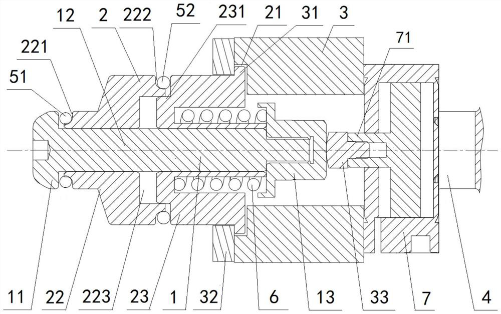
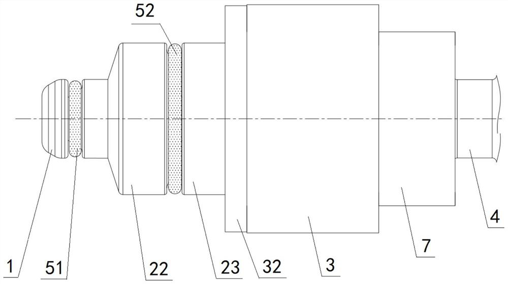
[0093] A multi-joint self-adaptive block, the self-adaptive block includes: a pushing shaft 1, a block body 2, and a casing 3; the front end of the casing 3 is provided with an annular groove 31, and the block body 2 The rear end of the housing 3 is fixedly connected with an annular baffle 21, and the annular baffle 21 is arranged in the annular groove 31. The front end of the housing 3 is fixedly provided with an annular end cover 32, and the rear end surface of the annular end cover 32 is in contact with the annular The front end face of the baffle plate 21 is limit-fitted, and a gap is provided between the outer wall of the annular baffle plate 21 and the inner wall of the annular groove 31, and a gap is provided between the inner wall of the central hole of the annular end cover 32 and the outer wall of the blocking body 2. The push-and-release shaft 1 includes a pressure block 11 and a shaft rod 12 of an integral structure, the front end of the shaft rod 12 is connected wi...

Embodiment 2

[0095] Embodiment 2 is basically the same as Embodiment 1, and its difference is:

[0096] The rear end of the housing 3 is fixedly connected to the front end of the drive cylinder 7, the cylinder body of the drive cylinder 7 is fixedly connected to the support 4, and the piston rod of the drive cylinder 7 is connected to the push rod 33; The push rod 33 includes a push head 331 and a second threaded rod 332 of an integral structure, the rear end of the push head 331 is fixedly connected to the front end of the second threaded rod 332, and the front end surface of the push head 331 is a spherical surface; The piston rod of the driving cylinder 7 is provided with a second threaded hole 71 , and the second threaded hole 71 is threadedly engaged with the second threaded rod 332 .

Embodiment 3

[0098] Embodiment 3 is basically the same as Embodiment 2, and its difference is:

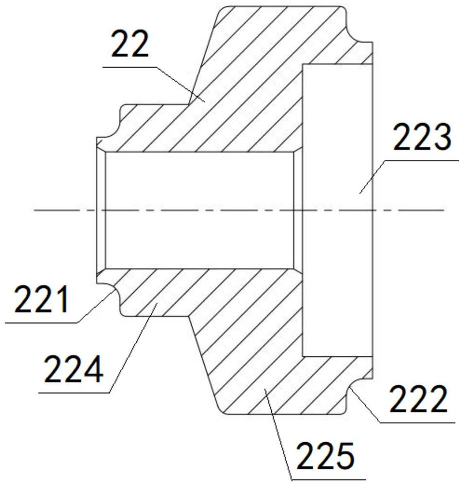
[0099] The plug 22 includes a first cylinder 224 and a second cylinder 225 of an integral structure, the rear end of the first cylinder 224 is fixedly connected to the front end of the second cylinder 225, and the first cylinder 224 is connected to the second cylinder 225. The cylinders 225 are coaxially arranged, the diameter of the first cylinder 224 is smaller than the diameter of the second cylinder 225; the first cylinder 224 and the second cylinder 225 are both sleeved on the outside of the shaft 12, and the first cylinder 224 and the second cylinder 225 are both slidingly fitted with the shaft rod 12, the front end of the first cylinder 224 is limitedly matched with the rear end of the pressure block 11, and the rear end of the second cylinder 225 is provided with a counterbore 223 ; The first sealing ring installation groove 221 is opened at the front end of the first cylinder 224, and ...


PUM


Abstract

A multi-joint self-adaptive plug comprises a pushing shaft, a plug body and a shell, the pushing shaft comprises a pressing block and a shaft rod which are of an integrated structure, the front end of the shaft rod is connected with the pressing block, the shaft rod is sleeved with the plug body, the plug body is in sliding fit with the shaft rod, and the rear end of the plug body is connected with the front end of the shell through a first movable joint; the front end of the plugging body is in limiting fit with the rear end of the pressing block, a first sealing ring is arranged between the plugging body and the pressing block, the rear end of the shaft rod is connected with the connecting body, the rear end face of the connecting body makes contact with the front end face of the push rod, the front end face of the push rod is a spherical crown curved surface, the push rod is arranged in the shell, and the connecting body and the push rod form a second movable joint. A spring is arranged between the connecting body and the plugging body, and the plugging body is in pressing fit with the connecting body through the spring. The two joints are arranged in the self-adaptive plug, so that concentricity of the plug body and the to-be-plugged hole can be achieved, bending or abrasion of the plug body can be avoided, and the service life of the plug is prolonged.

Description

technical field [0001] The invention relates to a sealing mechanism, in particular to a multi-joint self-adaptive sealing mechanism, which is particularly suitable for sealing experimental sealing of three-way stepped holes of automobile engine box parts. Background technique [0002] Cavity Leakage Test for Automobile Engine Cylinder Blocks, Cylinder Heads and Other Box Parts - Leak Test requires sealing specific planes and holes to form a test closed cavity. [0003] For the three-way stepped hole with open holes at both ends and the middle hole through the cavity, the sealing mechanism of the holes at both ends usually adopts rigid sealing or single-joint floating, and the sealing ring is set on the cylindrical surface. This design has the following disadvantages: the plugging head and the plugging hole are not concentric during the plugging process, and the plugging mechanism and the push rod of the drive cylinder are not concentric, resulting in unsmooth radial expansio...

Claims


Application Information

Patent Timeline
Patent Type & Authority Applications(China)
IPC IPC(8): G01M3/00
CPCG01M3/00
Inventor 阮涛柱金海涛何丹杨立学杜文博党荣利夏泉叶楠陈鹏韩亮
Owner DONGFENG AUTOMOBILE COMPANY
Why Eureka
Try Eureka