Vibration testing device capable of adjusting posture of automobile
A vibration test and adjustable technology, applied in vibration test, vehicle test, measuring device, etc., can solve problems such as flexible adjustment of vehicle posture, and achieve the effect of improving convenience and safety
- Summary
- Abstract
- Description
- Claims
- Application Information
AI Technical Summary
Problems solved by technology
Method used
Image

Examples
Embodiment 1
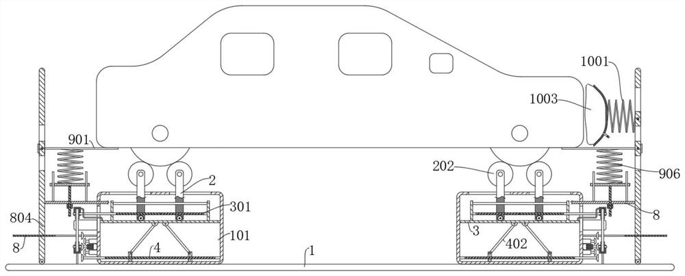
[0031] Refer Figure 1-7 A vibration test device that adjusts the car posture, includes a casing 101, further comprising a support shaft 201, and the support shaft 201 is located at the top of the casing 101 and is connected to the casing 101 through the attitude adjustment mechanism, and the attitude adjustment mechanism is connected to the casing The 101 extends to the top of the casing 101, the attitude adjusting mechanism includes; lifting mechanism connected to the casing 101 and the horizontal pitch adjustment mechanism attached to the lifting mechanism and extends the top of the casing 101.
[0032] The support shaft 201 is two of the symmetrical design, and is connected to two adjustment ends of the horizontal spacing adjustment mechanism, each of which is rotated over each of the support shafts 202, and the support shaft 201 and the test wheel 202 are passed. The bearing connection is provided with a test assembly on the test wheel 202.
[0033] At the time of the test, th...
Embodiment 2
[0039] Refer Figure 1-7 Further, in the basis of Example 1, it is further.
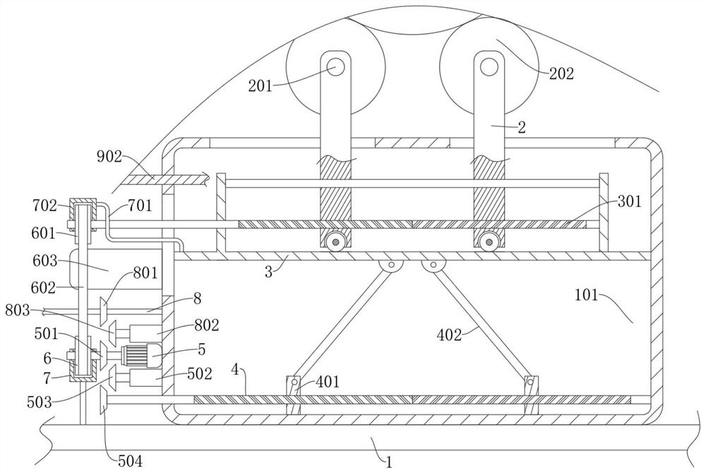
[0040] This example discloses a lifting mechanism including a second threaded rod 4 that is rotatably coupled to the inner wall of the casing 101, the second threaded rod 4 is a double threaded rod, and the thread is rotated in the second thread. The two threaded blocks 401 on the rod 4, respectively, respectively, respectively, respectively, respectively, on both ends of the second threaded rod 4 in which the second threaded rod 4 is rotated, and the upper and lower slides are attached to the lifting plate 3 of the inner wall of the casing 101, the bottom portion of the lifting plate 3 Turn two connecting rods 402 connected to the symmetric design, each of the connecting rods 402 is rotated on one end of the lifting plate 3, respectively, and the second threaded rod 4 is driven by a driving source, the second threaded rod 4 When rotating, the two threaded blocks 401 are simultaneously moved in opposite d...
Embodiment 3
[0045] Refer Figure 1-7 Further, in the basis of Example 2, it is further,
[0046] This example discloses a horizontal pitch adjustment mechanism including a first threaded rod 301 that is rotatably coupled to the lifting plate 3, and the first threaded rod 301 is a double threaded rod, and the threads threaded both ends, and threads. The two first support plates 2 connected to the first threaded rod 301, two first support plates 2 are respectively symmetrically connected to two support shafts 201 of the opposite first thread 301, symmetric design, respectively. The support shaft 201 can be fixed to the first support plate 2, respectively, and can be rotatably coupled to the first support plate 2, and the first threaded rod 301 can be rotatably coupled to the first support plate 2.
[0047] A slot is provided at the top of the casing 101, and the first support plate 2 slides in the slot.
[0048] Depending on the size of the car wheel, when the pitch of the two test wheel 202 is ...
PUM
 Abstract
Description
Claims
Application Information
 - R&D
- Intellectual Property
- Life Sciences
- Materials
- Tech Scout
- Unparalleled Data Quality
- Higher Quality Content
- 60% Fewer Hallucinations
Browse by: Latest US Patents, China's latest patents, Technical Efficacy Thesaurus, Application Domain, Technology Topic, Popular Technical Reports.
© 2025 PatSnap. All rights reserved.Legal|Privacy policy|Modern Slavery Act Transparency Statement|Sitemap|About US| Contact US: help@patsnap.com