Infrared optical fiber evanescent wave sensor for online detection and preparation method of infrared optical fiber evanescent wave sensor
An infrared light and sensor technology, used in instruments, measuring devices, scientific instruments, etc., can solve the problems of non-removable sensor probes, easy to be affected by water molecules in water, low sensitivity, etc., to enhance the evanescent field strength and save use. Cost, effect of improving sensitivity
Pending Publication Date: 2022-03-01
CENT FOR HYDROGEOLOGY & ENVIRONMENTAL GEOLOGY CGS
View PDF0 Cites 0 Cited by
- Summary
- Abstract
- Description
- Claims
- Application Information
AI Technical Summary
Problems solved by technology
Although the mid-infrared optical fiber spectral transmission technology has many advantages mentioned above, the sensitivity of the current mid-infrared optical
Method used
View moreImage
Smart ImageViewing Examples
Examples
 PUM
| Property | Measurement | Unit |
|---|---|---|
| Thickness | aaaaa | aaaaa |
| Thickness | aaaaa | aaaaa |
| Concentration | aaaaa | aaaaa |
Abstract
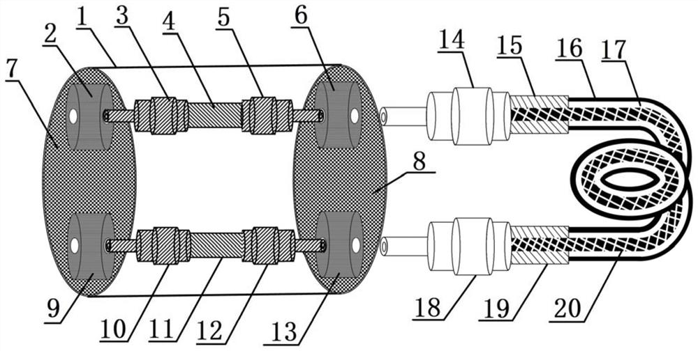
The invention relates to an infrared optical fiber evanescent wave sensor for online detection and a preparation method, and belongs to the technical field of electronic measurement devices. The sensor is composed of a sensing probe and a sensing probe fixing unit. The sensing probe fixing unit is composed of four optical fiber couplers, two intermediate infrared optical fibers, a cylindrical shell and two detachable mounting plates, the two ends of each intermediate infrared optical fiber are provided with optical fiber connectors, the optical fiber couplers are connected with the optical fiber connectors respectively, and the optical fiber couplers, the optical fiber connectors and the optical fibers are poured into a whole in the shell through packaging glue; the detachable mounting plates are mounted at the two ends of the shell, and the four optical fiber couplers are distributed on the two sides of the sensing probe fixing unit; the sensing probe is composed of a mid-infrared optical fiber and optical fiber connectors connected with the two ends of the mid-infrared optical fiber. The middle part of the mid-infrared optical fiber is composed of a mid-infrared optical fiber core, a chlorinated hydrocarbon capture polymer film and a super-hydrophobic film, wherein the chlorinated hydrocarbon capture polymer film and the super-hydrophobic film sequentially wrap the mid-infrared optical fiber core. According to the invention, online measurement of chlorinated hydrocarbon and other volatile organic compounds in the water body can be realized.
Description
technical field [0001] The invention relates to an infrared optical fiber evanescent wave sensor for online detection and a preparation method, in particular to an infrared optical fiber evanescent wave sensor for online detection of chlorinated hydrocarbon pollutants in water bodies, and belongs to the technical field of electronic measuring devices. Background technique [0002] Chlorinated hydrocarbons are a class of highly toxic, persistent and ubiquitous volatile pollutants that pose considerable risks to aquatic ecosystems and human health. They are often present in low concentrations and mixed with other pollutants in the aquatic environment, making in-line, accurate detection difficult. [0003] At present, the detection of chlorinated hydrocarbons usually adopts chromatographic or spectroscopic detection methods. Although these methods have high selectivity and high sensitivity, these methods require complex and time-consuming preconcentration and extraction steps,...
Claims
Login to View More Application Information
Patent Timeline
 IPC IPC(8): G01N21/01G01N21/3577
CPCG01N21/01G01N21/3577
Inventor 冯苍旭张建伟边超钟年丙
Owner CENT FOR HYDROGEOLOGY & ENVIRONMENTAL GEOLOGY CGS
Features
- R&D
- Intellectual Property
- Life Sciences
- Materials
- Tech Scout
- Unparalleled Data Quality
- Higher Quality Content
- 60% Fewer Hallucinations
Learn More Browse by: Latest US Patents, China's latest patents, Technical Efficacy Thesaurus, Application Domain, Technology Topic, Popular Technical Reports.
© 2025 PatSnap. All rights reserved.Legal|Privacy policy|Modern Slavery Act Transparency Statement|Sitemap|About US| Contact US: help@patsnap.com


