Eureka AIR delivers breakthrough ideas for toughest innovation challenges, trusted by R&D personnel around the world.

Single-satellite and ground-based equipment combined reentry forecasting method and device and electronic equipment

A ground-based and equipment technology, applied in measurement devices, satellite radio beacon positioning systems, radio wave measurement systems, etc., can solve problems such as affecting the accuracy of re-entry forecast, inability to accurately judge the final re-entry situation, and inability to achieve continuous monitoring. , to achieve high revisit rate, improve forecast accuracy, and achieve the effect of accurate discrimination

Active Publication Date: 2022-03-01
中国人民解放军32035部队
View PDF10 Cites 0 Cited by
  • Summary
  • Abstract
  • Description
  • Claims
  • Application Information

AI Technical Summary

Problems solved by technology

However, in the absence of global station deployment, the current ground-based equipment has a long revisit cycle for re-entry targets, and the ground-based tracking interval of some targets is even more than 16 hours, so continuous monitoring cannot be achieved, which seriously affects the accuracy of re-entry forecasts
Its accuracy is generally on the order of the orbital period, and the landing area covers the entire earth, so it is impossible to accurately judge the final reentry situation

Method used


Image

  • Single-satellite and ground-based equipment combined reentry forecasting method and device and electronic equipment
  • Single-satellite and ground-based equipment combined reentry forecasting method and device and electronic equipment
  • Single-satellite and ground-based equipment combined reentry forecasting method and device and electronic equipment

Examples


Embodiment Construction

[0057] The following will clearly and completely describe the technical solutions in the embodiments of the present invention with reference to the accompanying drawings in the embodiments of the present invention. Obviously, the described embodiments are only some, not all, embodiments of the present invention. Based on the embodiments of the present invention, all other embodiments obtained by persons of ordinary skill in the art without making creative efforts belong to the protection scope of the present invention.

[0058] In the existing technology, due to the limited deployment of ground-based detection equipment and too long monitoring intervals, it is difficult to accurately judge the re-entry events of large-scale space targets, and large-scale re-entry targets will have severe friction with the dense atmosphere during the re-entry process, resulting in The temperature rises gradually, and eventually it is ablated and disintegrated, and its high temperature and bright...


PUM


Abstract

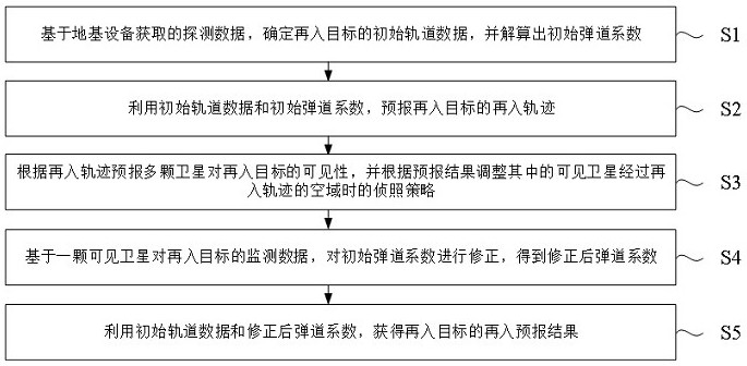
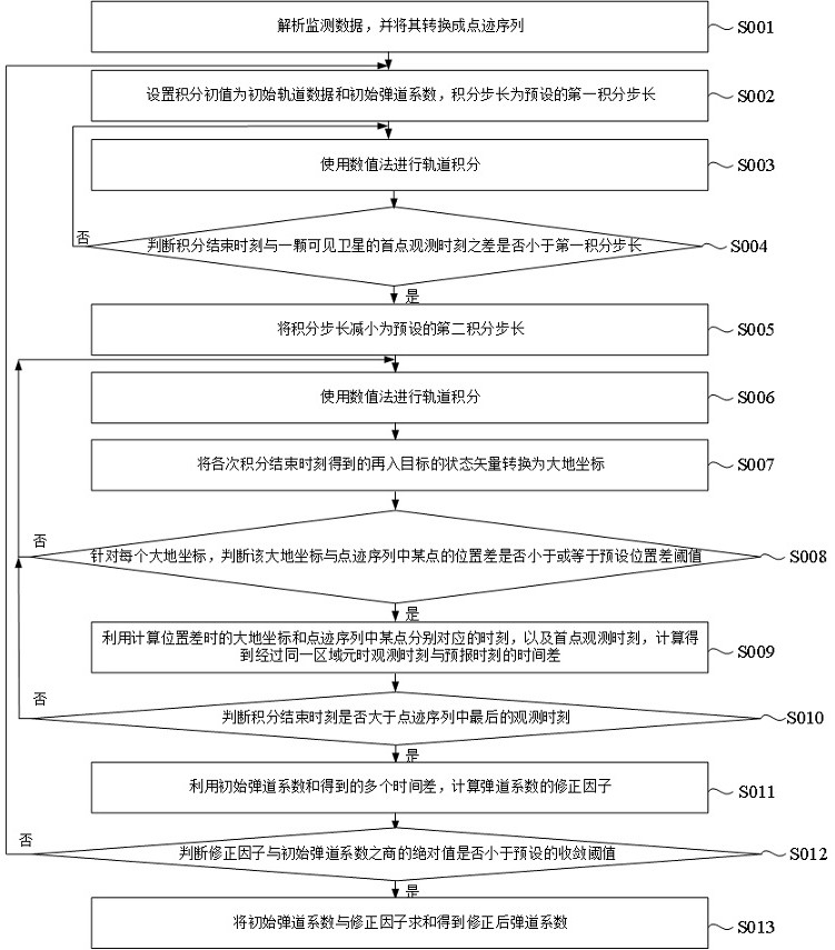
The invention discloses a single satellite and foundation equipment combined reentry forecasting method, which comprises the following steps of: determining initial orbit data of a reentry target based on detection data acquired by foundation equipment, and resolving an initial ballistic coefficient; forecasting a reentry trajectory of the reentry target by using the initial orbit data and the initial ballistic coefficient; forecasting the visibility of the multiple satellites to the reentry target according to the reentry trajectory, and adjusting a detection strategy when the visible satellites pass through the airspace of the reentry trajectory according to a forecasting result; correcting the initial ballistic coefficient based on monitoring data of a visible satellite on the reentry target to obtain a corrected ballistic coefficient; and obtaining a reentry forecast result of the reentry target by using the initial orbit data and the corrected ballistic coefficient. According to the method, the advantage of high revisit rate of the low-orbit giant constellation is utilized, the space-based satellite is guided through the ground-based detection data to monitor the reentry trajectory of the reentry target so as to correct the ballistic coefficient, so that the reentry target is forecasted, and the reentry forecasting precision can be improved.

Description

technical field [0001] The invention belongs to the field of aerospace measurement and control, and in particular relates to a reentry prediction method, device and electronic equipment combining a single satellite and ground-based equipment. Background technique [0002] After the low-orbit space objects orbiting the earth complete their missions, their orbital altitude will gradually decrease due to atmospheric resistance. Except for a few spacecraft that will safely return to the bottom surface under control, other objects will enter the atmosphere uncontrollably, that is, re-entry will occur. event. [0003] The large-mass space target will not be completely burned during the reentry process, and 10-40% of the debris will still return to the earth's surface, which will pose a great threat to the life groups, building facilities, and ecological environment on the surface. Also known as a dangerous reentry target. Maintaining continuous monitoring of dangerous re-entry t...

Claims


Application Information

Patent Timeline
IPC IPC(8): G01S19/42G01S19/26G01S19/27
CPCG01S19/42G01S19/26G01S19/27
Inventor 张炜王秀红马鑫崔文杨洋田鑫王臻泓陈思睿
Owner 中国人民解放军32035部队
Why Eureka
Eureka Blog
Learn More