
Optical element driving mechanism

A technology of optical components and driving mechanisms, applied in optical components, optical components, electrical components, etc., can solve problems such as vibration, shaking, and image blur, and achieve the effect of avoiding shaking, high stability and accuracy, and high precision.

Pending Publication Date: 2022-03-01
TDK TAIWAN
View PDF0 Cites 0 Cited by
  • Summary
  • Abstract
  • Description
  • Claims
  • Application Information

AI Technical Summary

Problems solved by technology

When the user uses the electronic device, shaking and vibration may occur, making the captured image blurred

Method used


Image

  • Optical element driving mechanism
  • Optical element driving mechanism
  • Optical element driving mechanism

Examples


Embodiment Construction

[0081] In this specification, many different embodiments or examples are provided, and relative spatial terms may be used to describe specific examples of various components and arrangements to implement different features of the present disclosure. For example, if the specification describes that the first feature is formed "on" and / or "above" the second feature, it means that it may include an embodiment in which the first feature is in direct contact with the second feature, and may also include the formation of additional features. An embodiment in which the first feature and the second feature are not in direct contact between the first feature and the second feature. Relative spatial relative terms are used to facilitate describing the relationship between elements or features and other elements or features in the drawings. These spatially relative terms are intended to encompass different orientations of the device in use or operation in addition to the orientation depi...


PUM


Abstract

The invention provides an optical element driving mechanism. The optical element driving mechanism comprises a fixed part, a movable part and a driving assembly. The movable part is connected with an optical element comprising an optical axis. The movable part can move relative to the fixed part. The driving assembly drives the movable part to move relative to the fixed part.

Description

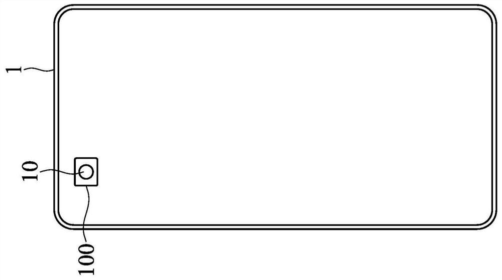
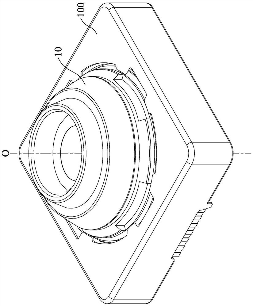
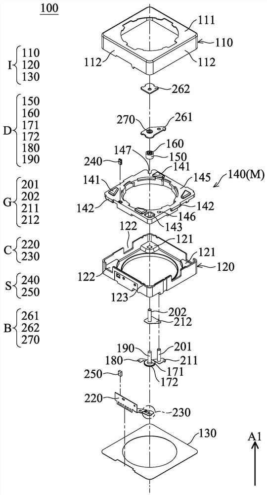
technical field [0001] The present disclosure relates to a driving mechanism, in particular to an optical element driving mechanism. Background technique [0002] With the development of technology, many electronic devices (such as smart phones or tablet computers) now have the function of taking photos or recording videos. Through the optical element and the optical element driving mechanism disposed on the electronic device, the user can operate the electronic device to capture images. When the user uses the electronic device, it may shake and vibrate, making the captured image blurred. Therefore, it is necessary to improve the quality of captured images. Contents of the invention [0003] The purpose of the present disclosure is to propose an optical element driving mechanism to solve at least one of the above problems. [0004] The present disclosure provides an optical element driving mechanism. The optical element driving mechanism includes a fixed part, a movabl...

Claims


Application Information

Patent Timeline
Patent Type & Authority Applications(China)
IPC IPC(8): G02B7/09G02B27/64G03B13/36G03B5/00H10N30/30
CPCG02B7/09G02B27/646G03B13/36G03B5/00G02B27/0006H02K41/0356H03K17/9517G02B7/021G02B7/04G02B13/001G03B2205/0069G03B30/00G03B3/10H04N23/55H10N50/10G02B7/02G02B26/0875G02B7/003G01L1/16G06F3/016H03K17/964H03K2217/96062G03B17/12H02K41/0354H04N23/685H10N30/302G02B7/1821G02B26/0816H04N23/54G03B5/02
Inventor 郑百叡陈树山张洁安胡朝彰
Owner TDK TAIWAN
Learn More