Charging wire sheath injection molding method

A charging cable and sheath technology, which is applied in the manufacture of circuits, electrical components, cables/conductors, etc., can solve the problems that the sheath cannot completely and evenly wrap the wire, increase the production process, and have miscellaneous edges, etc., and achieve strong anti-twist ability, Injection is quick and the injection thickness is uniform

Pending Publication Date: 2022-03-01
深圳市勤诚鑫科技有限公司
View PDF0 Cites 0 Cited by
  • Summary
  • Abstract
  • Description
  • Claims
  • Application Information

AI Technical Summary

Problems solved by technology

[0003] At present, for the injection molding process of the charging line, because the charging line that needs to be injected will have wires, and the length of the wires will be about 100mm, and the wires are very soft. When the wire is injected, the wire bursts out, so that the injected skin cannot completely and evenly wrap the wire. Therefore, most of them are injected by aligning the upper and lower molds. Injection molding the other side, but this injection molding method is easy to produce gaps at the cover, and there are likely to be miscellaneous edges at the cover after the cover, so subsequent grinding is required, thereby increasing redundant production processes

Method used


Image

  • Charging wire sheath injection molding method
  • Charging wire sheath injection molding method
  • Charging wire sheath injection molding method

Examples


Embodiment Construction

[0016] The embodiments of the present invention will be described in detail below with reference to the accompanying drawings, but the present invention can be implemented in many different ways defined and covered by the claims.

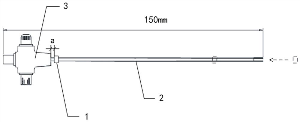
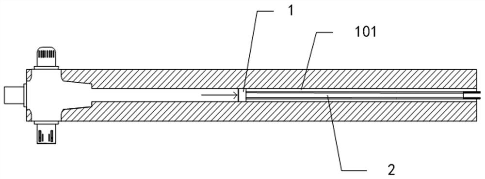
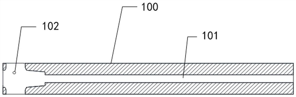
[0017] like Figure 1 to Figure 3 As shown, a method for injection molding a charging cable sheath provided in this embodiment includes the following steps:

[0018] S1. Prepare a copper ring 1. The diameter of the outer ring of the copper ring 1 needs to match the injection channel 101 of the injection mold 100, and the copper ring 1 is inserted into the wire 2 of the charging line, and then moved to the plug 3 and the wire 2. Where it connects, and reserve a gap a of 5-10mm;

[0019] S2. Put the charging cable through the copper ring 1 into the injection mold 100 of the injection molding machine as a whole, put the copper ring 1 upright in the injection channel 101, and keep waiting for injection molding;

[0020] S3, start injection molding, su...


PUM


Abstract

The invention discloses a charging wire sheath injection molding method. Comprising the following steps: S1, preparing a copper ring, enabling the copper ring to penetrate through a wire rod of a charging wire, moving the copper ring to a position where a plug is connected with the wire rod, and reserving a gap of 5-10 mm; s2, the whole charging wire with the copper ring penetrating is put into an injection mold of an injection molding machine, and the copper ring is erected in an injection molding channel and is kept to wait for injection molding; and S3, injection molding is started, injection molding is conducted from the position of the charging wire plug, when injection molding is conducted on the wire rod, an injection molding sizing material can push the copper ring to move outwards till injection molding of the wire rod is completed, and then the copper ring is taken down to complete injection molding of the wire rod. Before injection molding, the copper ring is additionally arranged to penetrate through the wire rod, the copper ring moves along with the injection molding rubber material, the effect of fixing the wire rod is achieved, the wire rod subjected to injection molding is always in the center state, it is guaranteed that the wire rod cannot be exposed to the surface of the injection molding rubber material due to position deviation, the process is simple, injection molding is rapid, and high practicability is achieved.

Description

technical field [0001] The invention relates to the technical field of industrial production fixtures, in particular to an injection molding method for a charging line sheath. Background technique [0002] During the production process of the charging line, after the charging line is initially formed, in order to improve the protection of the charging line, it is necessary to inject plastic on the periphery of the charging line, and wrap a layer of soft rubber around the charging line. [0003] At present, for the injection molding process of the charging line, because the charging line that needs to be injected will have wires, and the length of the wires will be about 100mm, and the wires are very soft. When the wire is injected, the wire bursts out, so that the injected skin cannot completely and evenly wrap the wire. Therefore, most of them are injected by aligning the upper and lower molds. Injection molding the other side, but this injection molding method is easy to ...

Claims


Application Information

Patent Timeline
Patent Type & Authority Applications(China)
IPC IPC(8): H01B13/22H01R43/24
CPCH01B13/22H01R43/24B29C2945/76531
Inventor 周瑞星
Owner 深圳市勤诚鑫科技有限公司
Why Eureka
Try Eureka