Power transformer
A technology for power transformers and transformers, applied in the field of transformers, can solve the problems of easy collision, heavy weight, collision between power transformers and forklifts or transfer tools, etc., and achieves the effect of avoiding damage and simple operation.
- Summary
- Abstract
- Description
- Claims
- Application Information
AI Technical Summary
Problems solved by technology
Method used
Image

Examples
Embodiment Construction
[0026] The following will clearly and completely describe the technical solutions in the embodiments of the present invention with reference to the accompanying drawings in the embodiments of the present invention. Obviously, the described embodiments are only some, not all, embodiments of the present invention. Based on the embodiments of the present invention, all other embodiments obtained by persons of ordinary skill in the art without making creative efforts belong to the protection scope of the present invention.
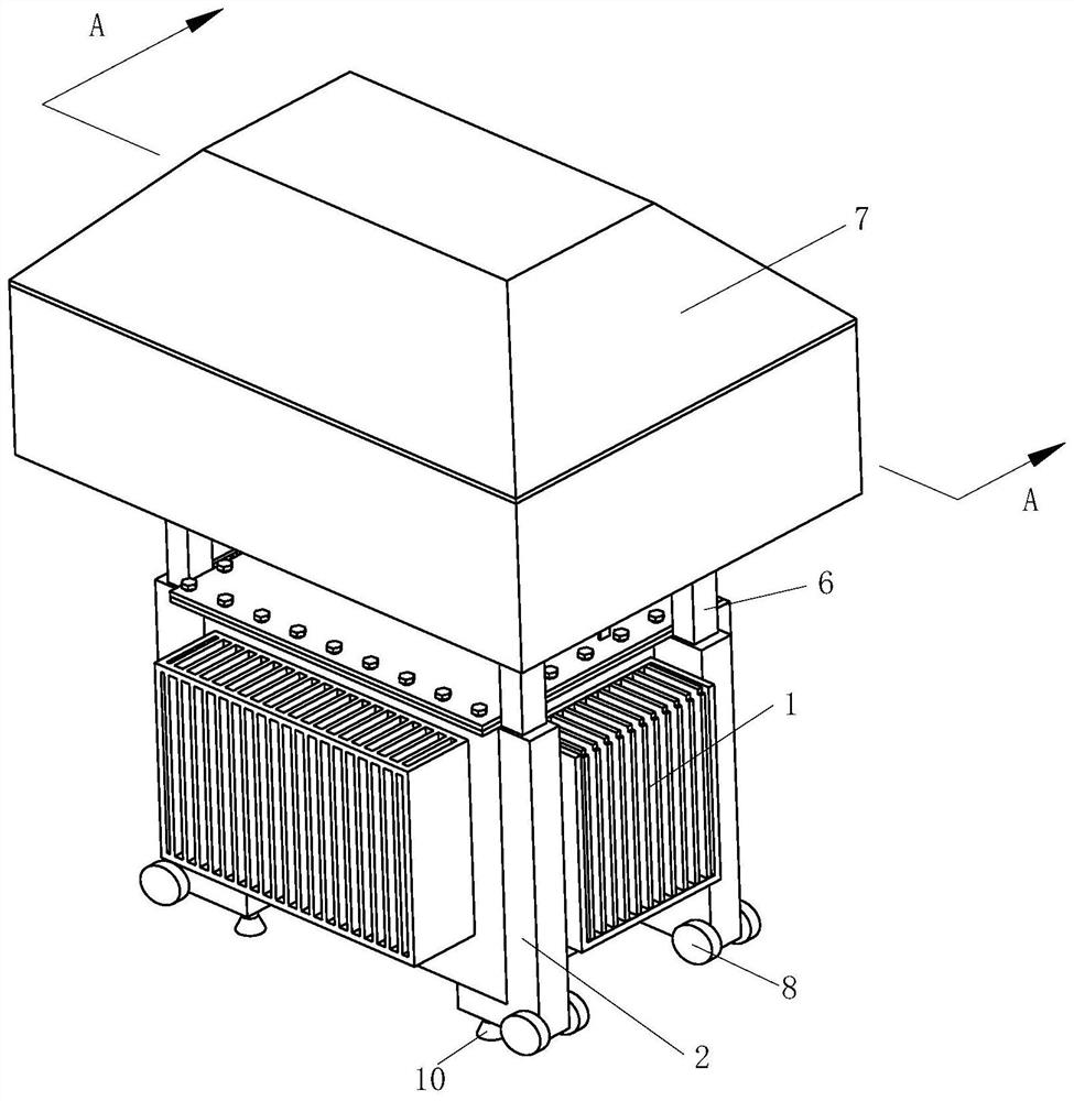
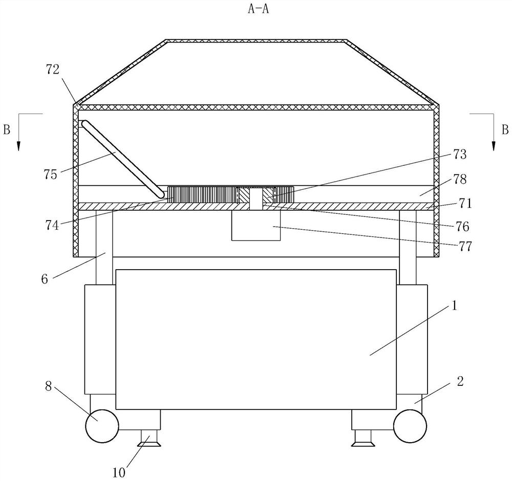
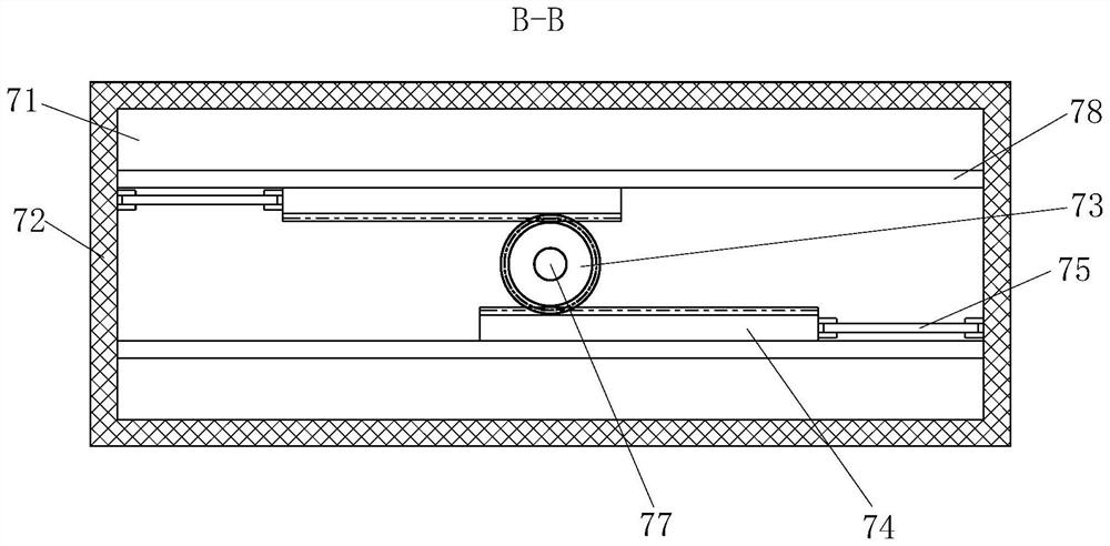
[0027] Such as Figure 1-4 As shown, a power transformer includes a transformer main body 1, four corners of the transformer main body 1 are provided with supporting columns 2, a chamber 3 is opened in the supporting column 2, and a chute 4 is opened on the front surface of the supporting column 2, and the sliding The groove 4 communicates with the first chamber 3, the chamber 3 is provided with a support device 5, the upper surface of the support column 2 is ...
PUM
 Abstract
Description
Claims
Application Information
PatSnap Eureka turns technology decisions into work you can execute. Powered by our Innovation Knowledge Graph, it runs expert workflows across engineering, life sciences, materials and intellectual property. Get your review-ready output in minutes.


