Protective manipulator for electrified maintenance of power equipment

A technology for live maintenance and electrical equipment, applied in the direction of manipulators, program-controlled manipulators, electrical components, etc., can solve problems such as inconvenience, time-consuming and labor-consuming operations, and loose terminal boards of aging secondary lines, so as to facilitate maintenance work and prevent The effect of screw collision damage

Active Publication Date: 2022-03-01
徐州鹏程电气有限公司
View PDF4 Cites 0 Cited by
  • Summary
  • Abstract
  • Description
  • Claims
  • Application Information

AI Technical Summary

Problems solved by technology

[0002]Power equipment mainly includes two categories of power generation equipment and power supply equipment. The power distribution cabinet used in power supply equipment has the functions of distributing power and controlling and monitoring circuits. In order to facilitate the better transmission of electric energy, the terminal board of the aging secondary line will become loose after the power distribution cabinet is used for a certain period of time. In order not to affect the normal transmission of power, it is necessary to carry out regular maintenance on the power distribution cabinet
[0003]However, traditionally, when overhauling the screws of the terminal board inside the power distribution cabinet, the staff wear insulating clothing and use a screwdriver to perform twisting and overhauling. It is very unsafe. Due to the high voltage inside the power distribution cabinet, it is easy to cause current breakdown and electric shock, and it is inconvenient to twist the screws when using a long screwdriver. The long-term operation is time-consuming and labor-intensive, which is very inconvenient and reduces the cost of maintenance. efficiency

Method used


Image

  • Protective manipulator for electrified maintenance of power equipment
  • Protective manipulator for electrified maintenance of power equipment
  • Protective manipulator for electrified maintenance of power equipment

Examples


Embodiment Construction

[0032] In order to make the technical means, creative features, goals and effects achieved by the present invention easy to understand, the present invention will be further described below in conjunction with specific embodiments.

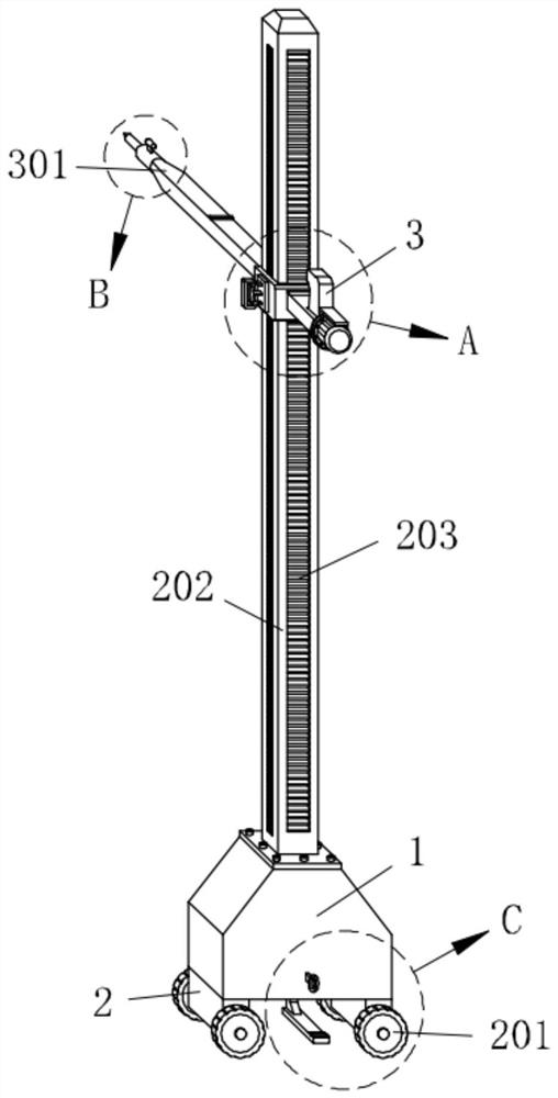
[0033] Such as Figure 1-Figure 10As shown, a protective manipulator for live maintenance of electric equipment according to the present invention includes a base 1, a support mechanism 2 is installed on the base 1, an overhaul mechanism 3 is installed on the support mechanism 2, and the support mechanism A control mechanism 4 is installed on the base 1, a brake mechanism 5 is installed inside the base 1, a stepping mechanism 6 is installed on the base 1, and a limit mechanism 7 is connected to the base 1.

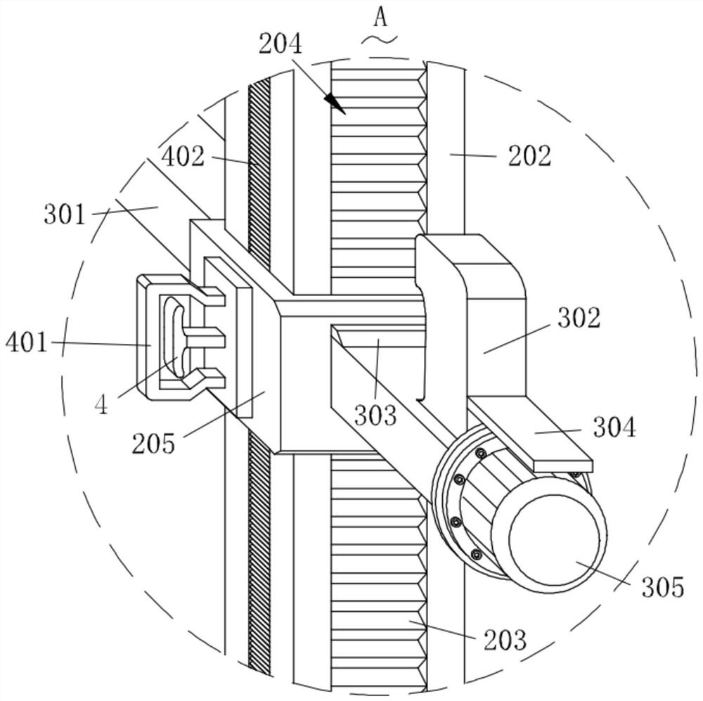
[0034] Specifically, the support mechanism 2 includes a column 202, the base 1 is detachably connected with the column 202, the two sides of the column 202 are provided with movable grooves 204, the inside of the column 202 is provided with a ...


PUM


Abstract

The invention relates to the technical field of power equipment maintenance, in particular to a protective manipulator for live maintenance of power equipment, which comprises a base, a supporting mechanism is mounted on the base, a maintenance mechanism is mounted on the supporting mechanism, a control mechanism is mounted on the supporting mechanism, and a brake mechanism is mounted in the base. A treading mechanism is mounted on the base, and a limiting mechanism is connected to the base; the maintenance mechanism is supported and slid through the supporting mechanism, the tightness of bolts in the electric cabinet can be conveniently and better maintained, the supporting mechanism is limited and controlled during adjustment under the action of the control mechanism, maintenance work is facilitated, the braking mechanism is controlled and driven through gliding resetting of the supporting mechanism, and therefore limiting braking of the supporting mechanism is achieved, and the maintenance efficiency is improved. The supporting mechanism is not prone to moving on the ground, the braking mechanism is driven by the treading and pressing mechanism and the limiting mechanism to act, and the braking mechanism can be controlled to conduct maintenance work during maintenance.

Description

technical field [0001] The invention relates to the technical field of power equipment maintenance, in particular to a protective manipulator for live maintenance of power equipment. Background technique [0002] Power equipment mainly includes two categories: power generation equipment and power supply equipment. The power distribution cabinet used in the power supply equipment has the functions of distributing power and controlling and monitoring the circuit, so as to facilitate better transmission of electric energy. After a period of time, the terminal board of the aging secondary line will become loose. In order not to affect the normal transmission of power, it is necessary to carry out regular maintenance on the power distribution cabinet. [0003] However, in the traditional way of overhauling the screws of the terminal board inside the power distribution cabinet, the staff wears insulated clothing and uses a screwdriver to perform twisting and overhauling, which is ...

Claims


Application Information

Patent Timeline
IPC IPC(8): H02B3/00B25J9/00B25J13/02
CPCH02B3/00B25J9/00B25J13/02
Inventor 张永孙瑶赵冰冰
Owner 徐州鹏程电气有限公司
Why Eureka
Try Eureka