
Power flow control system and method suitable for power transmission line of power system

A technology for power transmission lines and power flow control, which is applied to AC networks and electrical components of the same frequency with different sources, can solve problems such as large investment and difficult construction, and achieve the effect of improving stability and power quality and preventing overload

Pending Publication Date: 2022-03-01
NARI TECH CO LTD
View PDF0 Cites 0 Cited by
  • Summary
  • Abstract
  • Description
  • Claims
  • Application Information

AI Technical Summary

Problems solved by technology

Traditional solutions include measures such as building new lines and increasing line capacity. Although related problems can be solved, the investment is huge and the construction is extremely difficult. It is urgent to use new technical means to solve them.

Method used


Image

  • Power flow control system and method suitable for power transmission line of power system
  • Power flow control system and method suitable for power transmission line of power system
  • Power flow control system and method suitable for power transmission line of power system

Examples


Embodiment 1

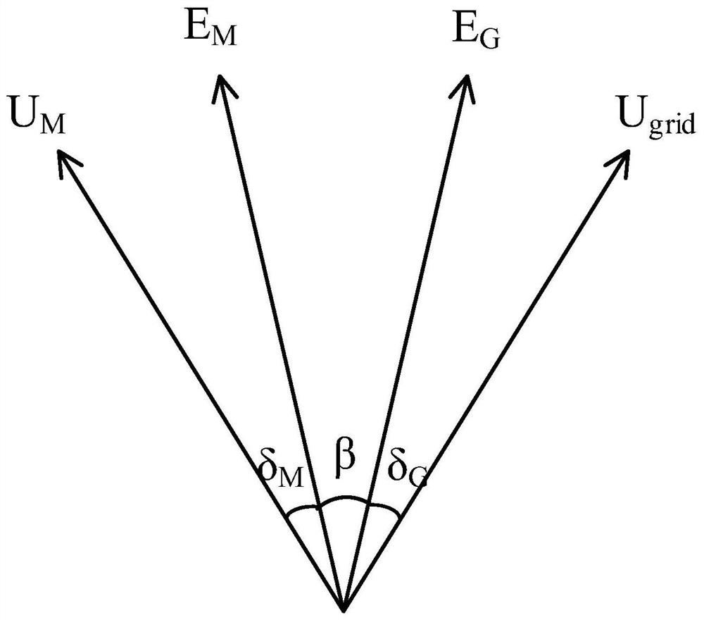
[0032] See attached figure 2 , when the excitation current I of the synchronous motor in the MGP unit fM Equal to synchronous generator excitation current I fG , since both the synchronous motor M and the synchronous generator G are connected to the large power grid, it is considered that the terminal voltage U of the synchronous motor in a certain period of time M and the terminal voltage U of the synchronous generator grid are unchanged, so U M and U grid The angle between them remains unchanged, and the power angles of the synchronous motor and the synchronous generator are respectively δ M and δ G , and δ M = δ G , the magnitude of the excitation potential E M =E G , the output power is P+jQ.

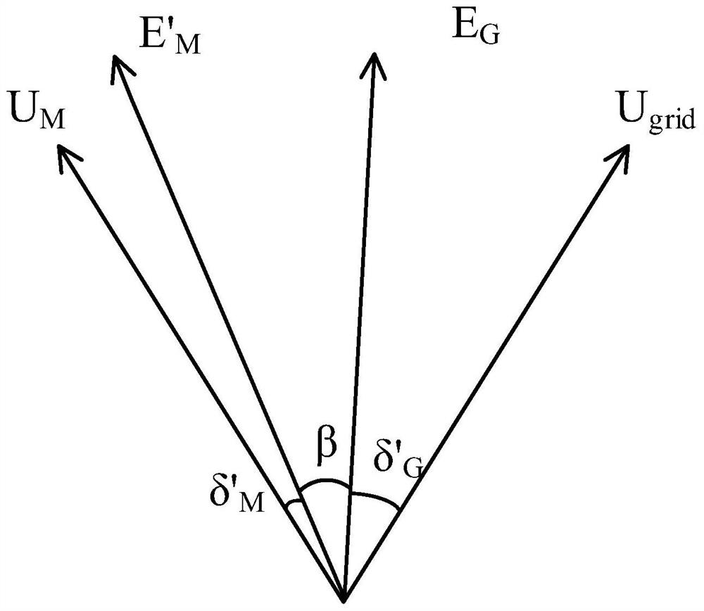
[0033] See attached image 3 , since the synchronous motor in the MGP unit is coaxially connected with the synchronous generator, the internal potential E of the two M and E G The phase angle difference of β remains unchanged, so in the attached figure 2 Based on, in...

Embodiment 2

[0043] An embodiment of the present invention provides a power flow control method suitable for a power system transmission line, the transmission line includes a first transmission line and a second transmission line connected in parallel, and the method includes:

[0044] Rigidly connecting the synchronous motor and the synchronous generator to the first transmission line in series;

[0045] Collect the active power of the first transmission line. When the active power and its load capacity in the first transmission line do not meet the preset requirements, adjust the excitation of the synchronous motor and synchronous generator in the MGP unit so that the active power in the first transmission line The load capacity meets the set requirements, and it is completed in the power flow control of the transmission line of the power system.

[0046] When the active power in the first transmission line is greater than the load capacity of the first transmission line, the excitation...


PUM


Abstract

The invention discloses a power flow control system and method suitable for power transmission lines of a power system. The system comprises a first power transmission line, a second power transmission line, an MGP unit and an adjusting unit, wherein the first power transmission line and the second power transmission line are connected in parallel; the MGP unit comprises a synchronous motor and a synchronous generator which are coaxially and rigidly connected and are connected in series in a first power transmission line; when it is monitored that the active power and the load capacity of the first power transmission line do not meet preset requirements, the adjusting unit adjusts excitation of a synchronous motor and excitation of a synchronous generator in the MGP unit, so that the active power and the load capacity of the first power transmission line meet the preset requirements, and power flow control over the power transmission line of the power system is completed. According to the invention, power flow adjustment can be flexibly and reliably carried out, thereby effectively avoiding the problems of uneven power flow distribution of a power sending-out channel, overload of a power transmission line and the like after electric energy is fed into a receiving end system, and ensuring safe and stable operation of a power grid.

Description

technical field [0001] The invention belongs to the technical field of power system stability and control, and in particular relates to a power flow control system and method suitable for power system transmission lines. Background technique [0002] At present, China is still in the transition period of UHV grid construction, and UHV AC grid is still one of the main grids for power transmission. Due to thermal stability, transient stability and dynamic stability problems, the transmission capacity of about 1 / 4 lines is limited, mainly concentrated in cross-regional AC interconnection lines and heavy-duty sections inside regional power grids. Traditional solutions include measures such as building new lines and increasing line capacity. Although related problems can be solved, the investment is huge and construction is extremely difficult, and new technical means are urgently needed to solve them. Contents of the invention [0003] In view of the above problems, the prese...

Claims


Application Information

Patent Timeline
IPC IPC(8): H02J3/06
CPCH02J3/06H02J2203/10
Inventor 吴维宁许其品杨玲孙竞轩王坤谢燕军刘国华
Owner NARI TECH CO LTD
Learn More