Steel plate moving device and moving method

A mobile device, steel plate technology, applied in the field of machinery, can solve problems such as low transfer efficiency and worker injury, and achieve the effects of improving transfer efficiency, ensuring stability and safety, and expanding the scope of application

Pending Publication Date: 2022-03-04
WECAN M&E SHANGHAI
View PDF0 Cites 0 Cited by
  • Summary
  • Abstract
  • Description
  • Claims
  • Application Information

AI Technical Summary

Problems solved by technology

[0004] The purpose of the present invention is to provide a steel plate moving device and a moving method, which are used to solve the problems in the prior art that the transfer efficiency is low due to manual transfer of steel plates, and workers are easily injured by the impact of steel plates

Method used


Image

  • Steel plate moving device and moving method
  • Steel plate moving device and moving method
  • Steel plate moving device and moving method

Examples


Embodiment 1

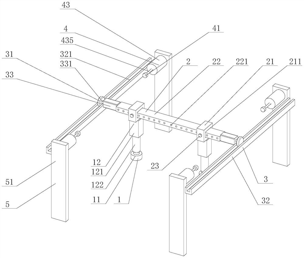
[0062] see Figure 1-Figure 2 , a steel plate moving device of this embodiment is applied to a steel plate truss production line, including:

[0063] Handle mechanism 1, is used for grasping steel plate (not shown in the figure) in vertical direction;

[0064] An adjustment mechanism 2, connected to at least one of the gripper mechanisms 1, for adjusting the position of the at least one gripper mechanism 1;

[0065] a moving mechanism 3, connected to the adjusting mechanism 2, and used to move the handle mechanism 1 in the horizontal direction;

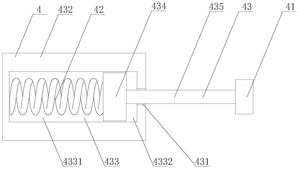
[0066] The buffer mechanism 4 is connected with the moving mechanism 3 and used for buffering the moving mechanism 3 .

[0067] The supporting frame 5 is connected with the buffer mechanism 4 and the moving mechanism 3 and is used for fixing the buffer mechanism 4 and the moving mechanism 3 .

[0068] The working principle of the above-mentioned technical scheme is: arranging the support frame 5 and the moving mechanism 3, so that th...

Embodiment 2

[0102] see Figure 1-Figure 3 , a steel plate moving method of the present embodiment, comprising:

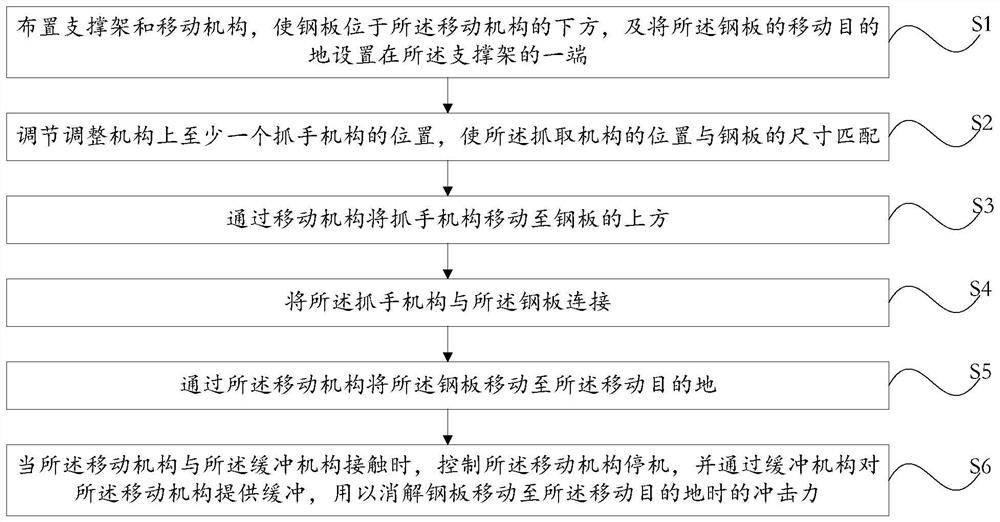
[0103] S1: arranging the support frame 5 and the moving mechanism 3 so that the steel plate is located below the moving mechanism 3, and setting the moving destination of the steel plate at one end of the support frame 5;

[0104] S2: adjusting the position of at least one handle mechanism 1 on the adjustment mechanism 2, so that the position of the handle mechanism 1 matches the size of the steel plate;

[0105] S3: Move the handle mechanism 1 to the top of the steel plate through the moving mechanism 3;

[0106] S4: connecting the gripper mechanism 1 with the steel plate;

[0107] S5: moving the steel plate to the moving destination through the moving mechanism 3;

[0108] S6: When the moving mechanism 3 is in contact with the buffer mechanism 4, control the moving mechanism 3 to stop, and provide buffering for the moving mechanism 3 through the buffer mechanism 4, so as t...


PUM


Abstract

The invention relates to the field of machinery, and discloses a steel plate moving device and method which are applied to a steel plate truss production line. The adjusting mechanism is connected with the at least one gripper mechanism and used for adjusting the position of the at least one gripper mechanism; the moving mechanism is connected with the adjusting mechanism and used for moving the gripper mechanism in the horizontal direction; the buffering mechanism is connected with the moving mechanism and used for buffering the moving mechanism; the supporting frame is connected with the buffering mechanism and the moving mechanism and used for fixing the buffering mechanism and the moving mechanism. The application range is expanded, the technical effect of automatically carrying steel plates is achieved, the steel plate transferring efficiency is improved, the risk that workers are injured is eliminated, and the stability and safety of steel plate carrying work are guaranteed.

Description

technical field [0001] The invention relates to the field of machinery, in particular to a steel plate moving device and a moving method. Background technique [0002] The current steel plate trusses are generally made of steel plates, in which the steel plates are cast with molten steel, cooled and pressed to form a flat steel, which is flat and rectangular, and can be directly rolled or cut from a wide steel strip. Steel plates are classified according to thickness, thin steel plates < 4 mm (thinnest 0.2 mm), medium-thick steel plates 4-60 mm, and extra-thick steel plates 60-115 mm. Steel plates are divided into hot-rolled and cold-rolled according to rolling. Truss is a structure composed of rods connected to each other with hinges at both ends. The truss is composed of straight rods and generally has a plane or space structure of triangular units. The truss members mainly bear axial tension or pressure, so that the strength of the material can be fully utilized. When...

Claims


Application Information

Patent Timeline
Patent Type & Authority Applications(China)
IPC IPC(8): B23Q7/04B23P23/06
CPCB23Q7/04B23P23/06
Inventor 张帅李鹏李艳艳高飞李苏斌
Owner WECAN M&E SHANGHAI
Why Eureka
Try Eureka