Tool holder for chip suction device and machine tool including same

一种吸引装置、工具保持的技术,应用在定位装置、机床零件、制造工具等方向,能够解决装置成本增加、难安装工具保持件、不能很好地保证尺寸精度等问题

Inactive Publication Date: 2014-02-12
DMG MORI CO LTD +1
View PDF6 Cites 8 Cited by
  • Summary
  • Abstract
  • Description
  • Claims
  • Application Information

AI Technical Summary

Problems solved by technology

Therefore, a plurality of suction devices are required, and there arises a problem of causing an increase in device cost
[0008] In addition, in the existing device, since the premise is that the tool holder side part and the main shaft side part of the chip suction path are tightly installed, it is difficult to reliably install the tool holder when the dimensional accuracy of the two parts cannot be well ensured. file problem

Method used


Image

  • Tool holder for chip suction device and machine tool including same
  • Tool holder for chip suction device and machine tool including same
  • Tool holder for chip suction device and machine tool including same

Examples


Embodiment 1

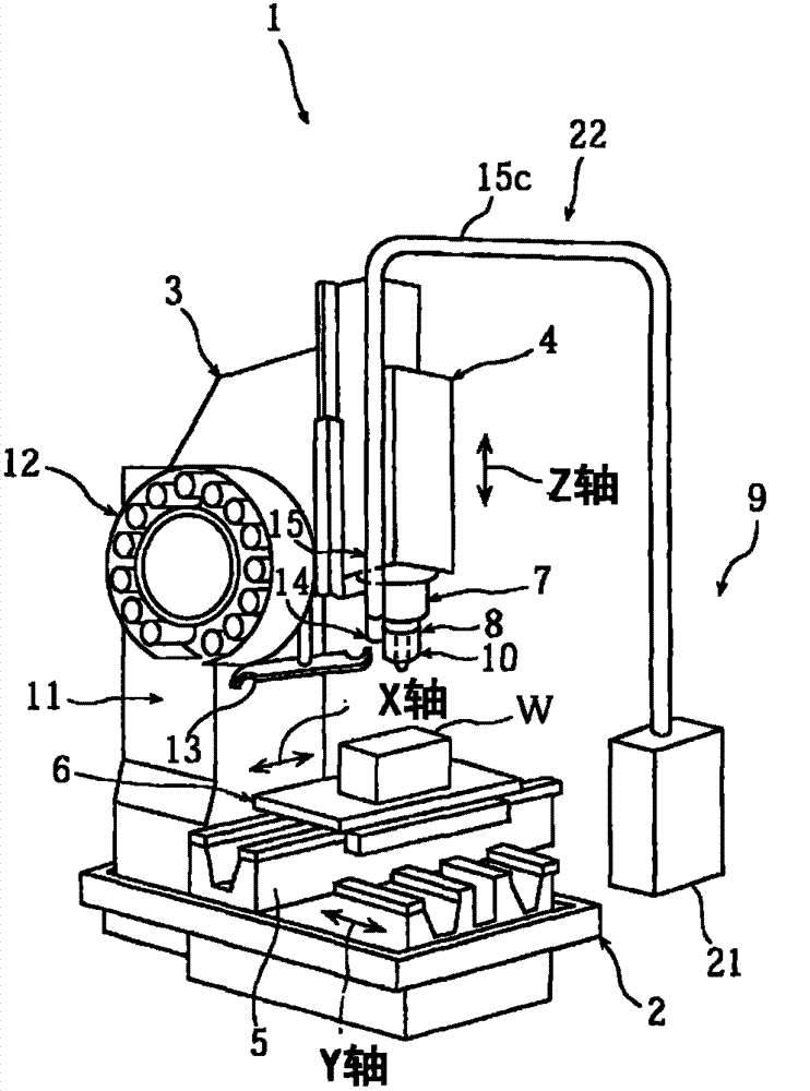
[0042] In the drawings, reference numeral 1 denotes a machine tool provided with the chip suction device tool holder according to the first embodiment of the present invention. This machine tool 1 is provided with a bed 2, a column 3 erected on the rear side when viewed from the front of the bed 2, and a spindle head 4 supported so as to be movable in the vertical direction (Z-axis direction) on the front surface of the column 3. , a base (saddle) 5 supported on the front part of the base 2 so as to be movable in the front-rear direction (Y-axis direction), and a worktable supported on the base 5 so as to be movable in the left-right direction (X-axis direction) (table)6. Furthermore, a tool changing device 11 having a tool magazine 12 , a tool changing arm 13 and the like is provided on a side surface of the column 3 .

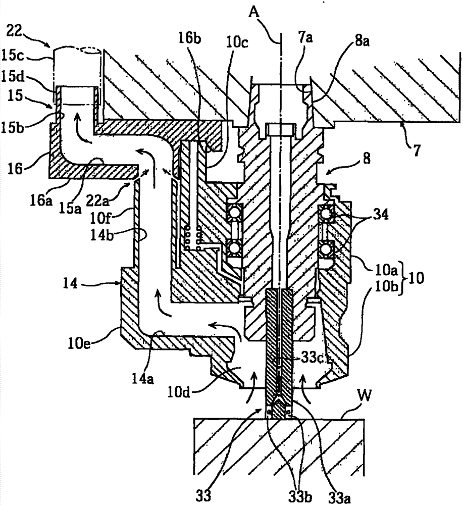
[0043] The spindle 7 is inserted into the spindle head 4 and is rotatably supported. Furthermore, a tool holder 8 is detachably attached to the lower end p...


PUM


Abstract

A connection portion 22a between a holder side part 14 of a chip suction path 12 and a main body side part 15 of the chip suction hath 12 is formed to have a non-contact structure, resulting in that not only a chip generated at a machining point but also a chip remained so as to be suspended in a machining atmosphere can be sucked and discharged.

Description

technical field [0001] The present invention relates to a tool holder for a chip suction device, and more particularly to improvement of suction of chips in machining air and mountability of the tool holder to a spindle. Background technique [0002] The chip suction device includes a tool holder and an external suction type suction path provided to communicate with the outside of the main shaft. With such an external suction path, when the tool holder is attached to the spindle, it is necessary to airtightly connect the suction path on the tool holder side and the suction path on the spindle side. In this case, there is a problem that if cutting chips remain in the connecting portion of the two passages, the connection cannot be reliably performed. [0003] Therefore, in Patent Document 1, the tool holder side part and the main shaft side part of the suction passage are arranged to face each other with a gap, and either one of them is set to expand and contract, and when t...

Claims


Application Information

Patent Timeline
Patent Type & Authority Applications(China)
IPC IPC(8): B23Q11/00B23Q3/12
CPCB23Q11/0046B23Q2220/008Y02P70/10
Inventor 秀田守弘佐藤康児大出久幸松尾晋哉中畑达雄
Owner DMG MORI CO LTD
Why Eureka
Try Eureka