Automatic glaze spraying device for suspension type porcelain insulator
A technology of porcelain insulators and glaze spraying, applied in insulators, ceramic molding machines, electrical components, etc., can solve problems such as uniform glazing of difficult ceramic insulators, and achieve the effects of preventing precipitation and promoting glazing efficiency and quality.
- Summary
- Abstract
- Description
- Claims
- Application Information
AI Technical Summary
Problems solved by technology
Method used
Image
Examples
Embodiment 1
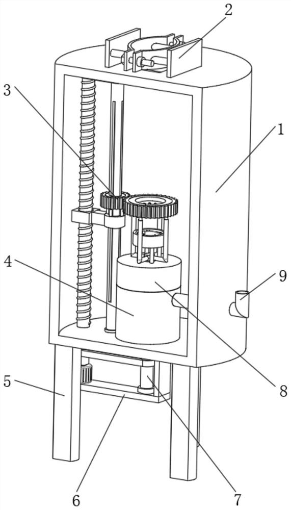
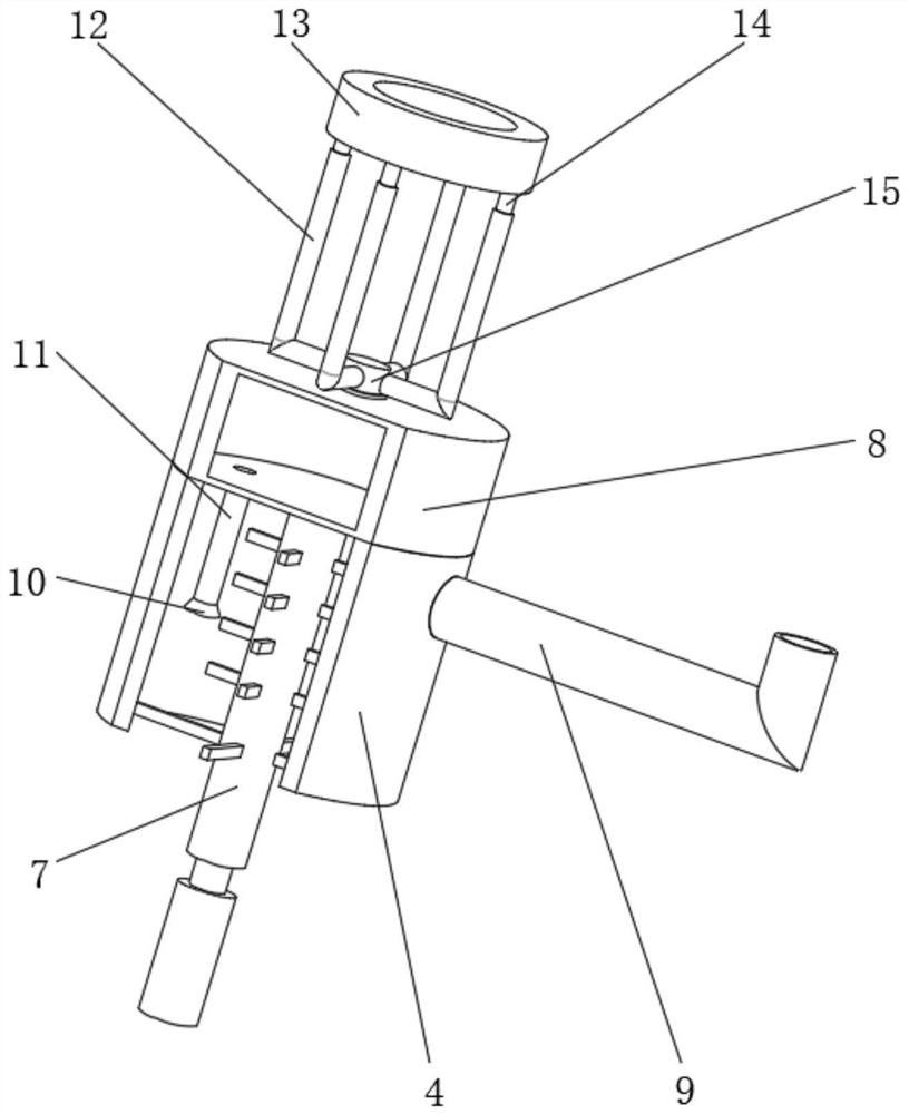
[0030] Embodiment one, by Figure 1-Figure 8 Given, the present invention includes a working box 1, the bottom of the working box 1 is fixedly equipped with support legs 5 at equal angles, the bottom of the inner cavity of the working box 1 is fixedly installed with a glaze storage box 4, and the right side of the glaze storage box 4 is fixedly installed with an advanced The right end of the glaze pipe 9 and the glaze inlet pipe 9 runs through the right side of the working box 1, the top of the glaze storage box 4 is fixedly installed with a glaze discharge bin 8, the interior of the work box 1 is equipped with a porcelain insulator fixing mechanism 2, and the glaze storage box 4 A stirring mechanism 7 is installed inside, and a uniform glaze spraying mechanism 3 is installed in the inner cavity of the working box 1. The uniform spraying glaze mechanism 3 is connected with the glaze outlet chamber 8. The bottom of the working box 1 is fixedly installed with a bottom plate 6, an...
Embodiment 2
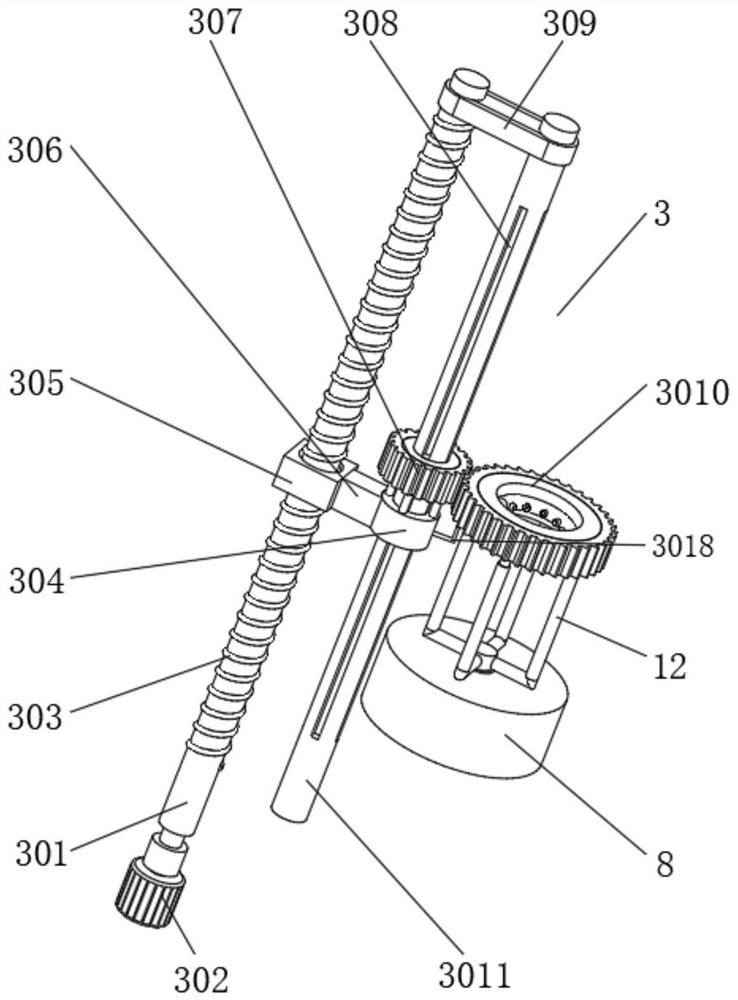
[0031]Embodiment 2. On the basis of Embodiment 1, the uniform glaze spraying mechanism 3 includes a drive shaft 301 that is located inside the work box 1 and is movably connected with the work box 1. The bottom end of the drive shaft 301 runs through the bottom of the work box 1 and is fixedly connected with a The motor 302, the bottom of the motor 302 is fixedly connected with the base plate 6, the outside of the drive shaft 301 is provided with an external thread 303, the drive shaft 301 is threaded with a threaded sleeve 305 through the external thread 303, and the internal movement of the working box 1 is connected with a drive shaft. The driven shaft 3011 on the right side of 301, the first conveyor belt 309 is movably connected between the driven shaft 3011 and the driving shaft 301, the support sleeve 304 is movably connected to the outside of the driven shaft 3011, and the left side of the support sleeve 304 is fixedly connected with a connection Block 306, the left sid...
Embodiment 3
[0033] Embodiment 3, on the basis of Embodiment 1, the stirring mechanism 7 includes a stirring shaft 701 that is movably connected with the bottom plate 6, the top of the stirring shaft 701 runs through the bottom of the working box 1 and is movably connected with the bottom of the glaze chamber 8, and the stirring shaft 701 Stirring rod 703 is fixedly installed equidistantly on the outer side of the stirring rod 703, and the stirring rod 703 is positioned at the inside of the glaze storage box 4, and a scraping rod 704 is fixedly installed at an equal angle on the outside of the stirring shaft 701, and the scraping rod 704 is positioned at the bottom of the stirring rod 703 and is connected with the storage glaze The bottom of the inner cavity of the box 4 is attached, and the outside of the stirring shaft 701 and the driving shaft 301 is movably connected with a second conveyor belt 702 located below the working box 1;
[0034] When the motor 302 drives the drive shaft 301 t...
PUM
 Abstract
Description
Claims
Application Information
 - R&D
- Intellectual Property
- Life Sciences
- Materials
- Tech Scout
- Unparalleled Data Quality
- Higher Quality Content
- 60% Fewer Hallucinations
Browse by: Latest US Patents, China's latest patents, Technical Efficacy Thesaurus, Application Domain, Technology Topic, Popular Technical Reports.
© 2025 PatSnap. All rights reserved.Legal|Privacy policy|Modern Slavery Act Transparency Statement|Sitemap|About US| Contact US: help@patsnap.com


