
High-precision quantitative feeding belt weigher

A technology of quantitative feeding and belt scales, which is applied in the direction of weighing, measuring devices, and weighing equipment for continuous material flow. The effect of preventing accumulation and avoiding material accumulation

Pending Publication Date: 2022-03-04
徐州圣能科技有限公司
View PDF0 Cites 0 Cited by
  • Summary
  • Abstract
  • Description
  • Claims
  • Application Information

AI Technical Summary

Problems solved by technology

[0004] The object of the present invention is to provide a quantitative feeding belt scale with high precision to solve the problem that when the existing belt scale proposed in the above background technology is feeding, if the material accumulates in the feeding frame, the falling speed of the material will change. Slow, so that it is impossible to feed quantitatively, which affects the occurrence of errors and the problem of inconvenient use

Method used


Image

  • High-precision quantitative feeding belt weigher
  • High-precision quantitative feeding belt weigher
  • High-precision quantitative feeding belt weigher

Examples


Embodiment 1

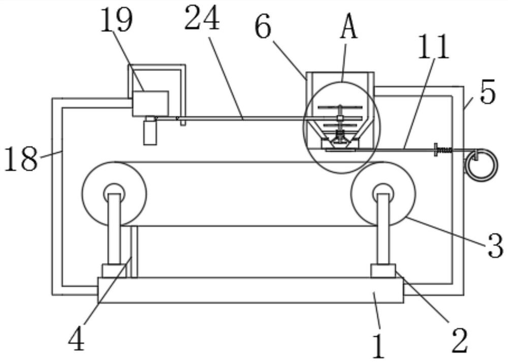
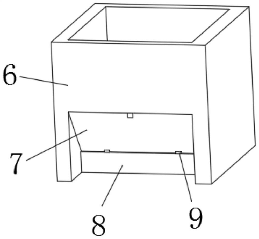
[0039] refer to Figure 1-6 A quantitative feeding belt scale with high precision is shown, including a base 1, four load cells 2 are installed on the top of the base 1, a weighing belt 3 is installed on the top of the four load cells 2, and a weighing belt 3 is installed on the top of the base 1 A scraper 4 is installed, and the scraper 4 is installed in cooperation with the weighing belt 3. A U-shaped mounting rod 5 is installed on the side of the base 1, and a feeding frame 6 is installed on the top of the U-shaped mounting rod 5. The side of the feeding frame 6 There are two through-holes on the upper part, the inner walls of the two through-holes are equipped with a material guide slant plate 7, and the bottoms of the two material guide slant plates 7 are slidingly installed with a material guide trapezoidal plate 8, and the side of the U-shaped installation rod 5 An intermittent feeding mechanism is installed at the top, which corresponds to the position of the guide tra...

Embodiment 2

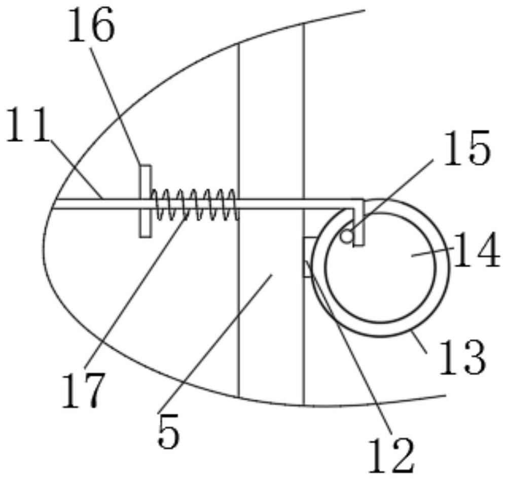
[0042] Based on above-mentioned embodiment 1, intermittent feeding mechanism comprises the connecting column 12 that is installed in U-shaped mounting bar 5 side parts, and the end of connecting column 12 is equipped with driving motor 13, and the output end of driving motor 13 is equipped with driving plate 14, drives An extruding head 15 is installed eccentrically on the side of the disk 14, and a sliding hole is opened on the side of the U-shaped mounting rod 5, and an L-shaped extruding rod 11 is slidably installed in the sliding hole, and the L-shaped extruding rod 11 and the extruding head 15 The sides of the L-shaped extruding rod 11 are connected with an elastic unit, and the end of the L-shaped extruding rod 11 away from the drive motor 13 is equipped with a blocking plate 10, which is connected to the two guide trapezoidal plates 8. corresponding to the location. Start the drive motor 13, the output end of the drive motor 13 rotates to drive the drive plate 14 to rot...

Embodiment 3

[0044] Based on the above-mentioned embodiment 1 or 2, the elastic unit includes a limit plate 16 fixedly sleeved on the L-shaped extruding rod 11, and a limit spring 17 is sleeved on the L-shaped extruding rod 11, and one end of the limit spring 17 is connected to the limit plate. The side of the position plate 16 is connected, and the other end of the limit plate 16 is connected with the side of the U-shaped mounting rod 5 . The movement of the L-shaped extruding rod 11 drives the limit plate 16 to move, and the movement of the limit plate 16 causes the limit spring 17 to deform, and the force of the limit spring 17 facilitates the recovery of the limit plate 16 to its original shape.


PUM


Abstract

The invention relates to the technical field of belt weighers, in particular to a high-precision quantitative feeding belt weigher which comprises a base, four weighing sensors are installed on the top of the base, a weighing belt is installed on the tops of the four weighing sensors, a scraper is installed on the top of the base, the scraper and the weighing belt are installed in a matched mode, and the scraper and the weighing belt are installed in a matched mode. A U-shaped mounting rod is mounted on the side portion of the base, a feeding frame is mounted at the top end of the U-shaped mounting rod, and two through holes are formed in the side portion of the feeding frame. During feeding, materials can be put in through the feeding frame, and when the materials do not reach the standard, the output end of a telescopic hydraulic cylinder stretches out to drive a telescopic shaft and a baffle to move downwards, so that the materials are fed into the feeding frame; and meanwhile, the anti-blocking mechanism can be driven to rotate, so that the materials are prevented from being accumulated in the feeding frame, and two material guide trapezoidal plates are pushed to be away from each other, so that a discharge port is enlarged, and the materials can quickly reach the specified weight.

Description

technical field [0001] The invention relates to the technical field of belt scales, in particular to a quantitative feeding belt scale with high precision. Background technique [0002] A belt scale is a weighing instrument that automatically weighs loose materials that are placed on a belt and pass continuously with the belt. [0003] When the existing belt scale is feeding, if the material accumulates in the feeding frame, the falling speed of the material will slow down, so that the quantitative feeding cannot be carried out, which will affect the error and make it inconvenient to use. In view of this, we propose a A quantitative feeding belt scale with high precision. Contents of the invention [0004] The object of the present invention is to provide a quantitative feeding belt scale with high precision to solve the problem that when the existing belt scale proposed in the above background technology is feeding, if the material accumulates in the feeding frame, the f...

Claims


Application Information

Patent Timeline
IPC IPC(8): G01G11/08
CPCG01G11/08Y02A40/81
Inventor 吴先锋王静段涛
Owner 徐州圣能科技有限公司
Learn More