Wheel designs for use within a track assembly of a work vehicle

a technology for work vehicles and wheels, applied in endless track vehicles, vehicles, transportation and packaging, etc., can solve the problems of mud/debris build-up within the interior of the wheels, current track wheels are often quite difficult to clean, and conventional track wheel designs currently experience problems such as accumulation of such materials

Active Publication Date: 2019-03-12
BLUE LEAF I P INC
View PDF26 Cites 0 Cited by
  • Summary
  • Abstract
  • Description
  • Claims
  • Application Information

AI Technical Summary

Benefits of technology

[0007]In another aspect, the present subject matter is directed to a track wheel for use within a track assembly of a work vehicle. The track wheel may include a wheel rim having an outer rim wall extending axially between a first side and a second side of the track wheel. The wheel rim may also include a first side wall extending radially inwardly from the outer rim wall along the first side of the wheel such that an inner end of the first side wall is spaced radially inwardly from the outer rim wall. The track wheel may also include a hub disc extending radially within the wheel rim between a radially inner end and a radially outer end. The radially inner end may define a central opening configured to receive at least a portion of a hub assembly of the work vehicle. The radially outer end may be positioned adjacent to a portion of the wheel rim. In addition, the track wheel may include means for preventing material accumulation within an interior space of the track wheel, wherein the interior space is defined radially inwardly from the outer rim wall and extends axially between the first side wall and the hub disc.

Problems solved by technology

Due to the typical operating environment for a work vehicle, track assemblies are often exposed to mud and / or debris, which can lead to accumulation of such material within one or more of the components of a track assembly.
As such, conventional track wheel designs currently experience issues with mud / debris build-up within the interior of the wheels.
In addition, due to their design, current track wheels are often quite difficult to clean.

Method used


Image

  • Wheel designs for use within a track assembly of a work vehicle
  • Wheel designs for use within a track assembly of a work vehicle
  • Wheel designs for use within a track assembly of a work vehicle

Examples


Embodiment Construction

[0020]Reference now will be made in detail to embodiments of the invention, one or more examples of which are illustrated in the drawings. Each example is provided by way of explanation of the invention, not limitation of the invention. In fact, it will be apparent to those skilled in the art that various modifications and variations can be made in the present invention without departing from the scope or spirit of the invention. For instance, features illustrated or described as part of one embodiment can be used with another embodiment to yield a still further embodiment. Thus, it is intended that the present invention covers such modifications and variations as come within the scope of the appended claims and their equivalents.

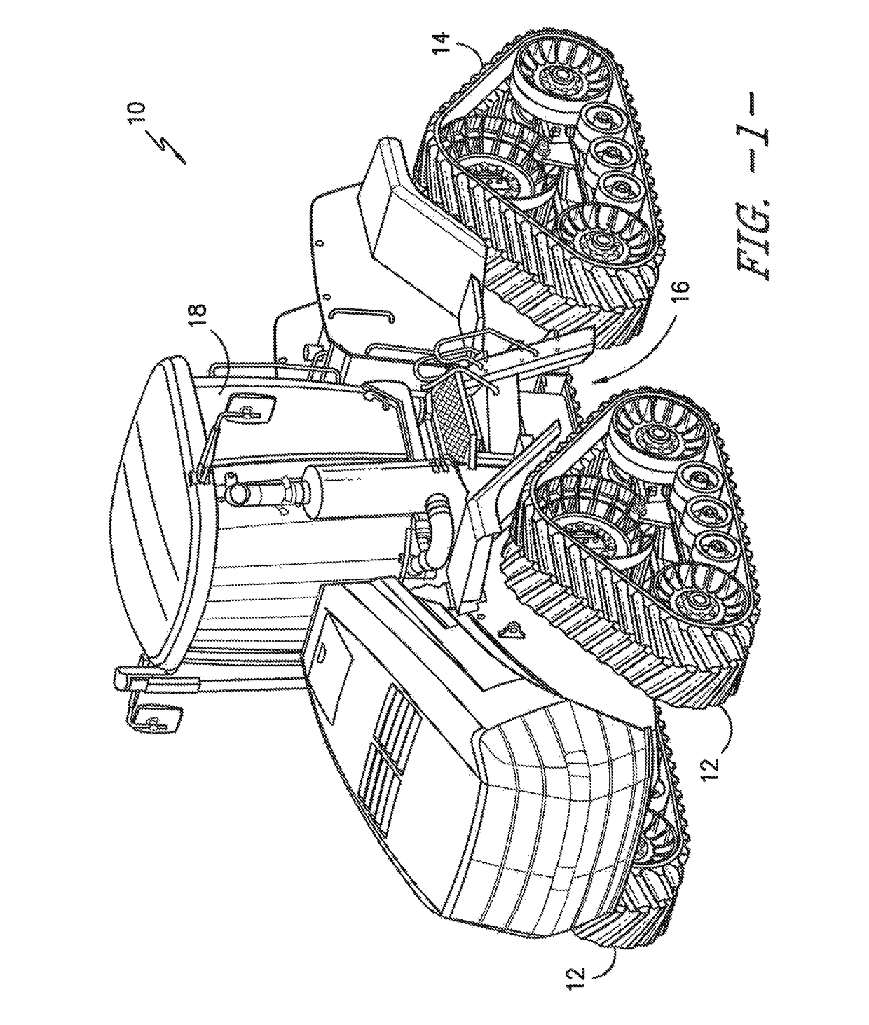
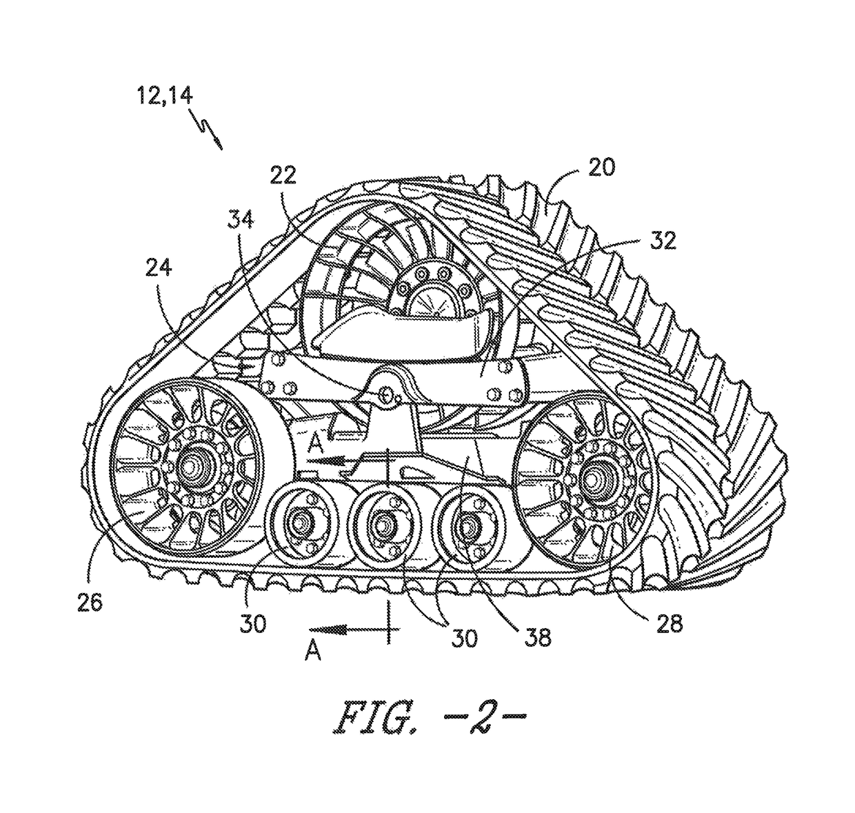
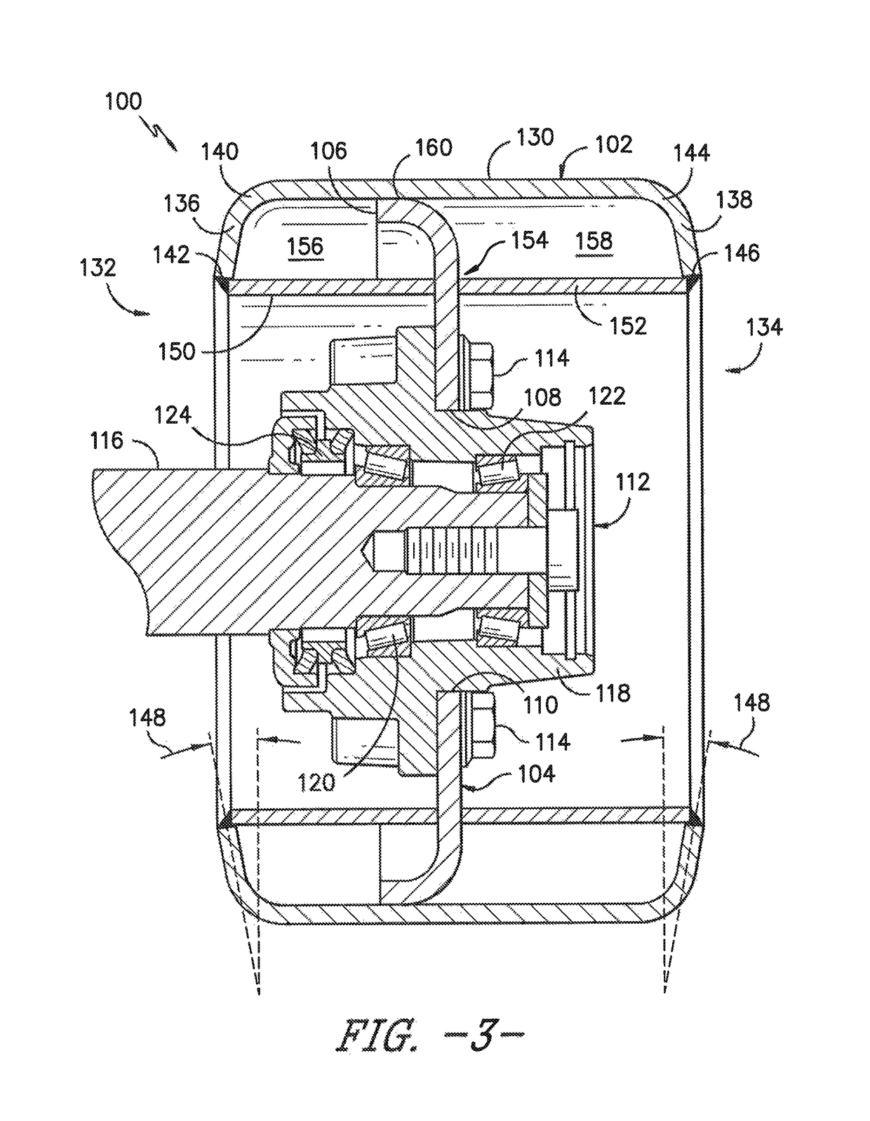
[0021]In general, the present subject matter is directed to improved wheel designs for use within a track assembly of a work vehicle. Specifically, in several embodiments, the disclosed track wheel may include a wheel rim and a hub disc extending radially w...


PUM


Abstract

A track wheel may include a wheel rim having an outer rim wall extending axially between first and second sides of the track wheel. The wheel rim may also include a first side wall extending radially inwardly from the outer rim wall along the first side of the wheel such that an inner end of the first side wall is spaced radially inwardly from the outer rim wall. The track wheel may also include a hub disc extending radially within the wheel rim between an inner end and an outer end. In addition, the track wheel may include a first shield wall extending axially between the inner end of the first side wall and the hub disc. The first shield wall may be spaced radially inwardly from the outer rim wall such that a radial gap is defined between the first shield wall and the outer rim wall.

Description

FIELD OF THE INVENTION[0001]The present subject matter relates generally to work vehicles and, more particularly, to improved wheel designs for use within a track assembly of a work vehicle.BACKGROUND OF THE INVENTION[0002]Current work vehicles, such as tractors and other agricultural vehicles, include an electronically controlled engine and a transmission, such as a power shift transmission (PST) or a continuously variable transmission (CVT), coupled to the engine. The transmission is, in turn, coupled to at least one drive axle assembly for transferring torque from the transmission to the vehicle's wheels or tracks. For instance, for a four-wheel drive track-driven vehicle, a drive wheel of each front track assembly is typically rotationally coupled to a front axle assembly of the work vehicle for transferring torque transmitted from the engine to the front track assembly while a drive wheel of each rear track assembly is typically rotationally coupled to a rear axle assembly of t...

Claims


Application Information

Patent Timeline
Patent Type & Authority Patents(United States)
IPC IPC(8): B62D55/14B62D55/088B62D55/065
CPCB62D55/14B62D55/088B62D55/065
Inventor VIK, BRIANTVEITO, DAVID L.STOLTMAN, RUSSELL V.
Owner BLUE LEAF I P INC
Why Eureka
Try Eureka