A microfilter for solid-liquid separation

A solid-liquid separation and micro-filter technology, applied in separation methods, filtration separation, moving filter element filters, etc., can solve the problems of reducing filtration efficiency, accumulation, impacting the filter layer, etc., to improve the utilization rate and effect, uniformity Filtering effect, fast filtering and discharging effect

Active Publication Date: 2021-12-31
深圳市树立水处理设备有限公司
View PDF17 Cites 0 Cited by
  • Summary
  • Abstract
  • Description
  • Claims
  • Application Information

AI Technical Summary

Problems solved by technology

[0003] 1. The microfilter needs to backwash the filter cartridge frequently, so as to realize the clogging and cleaning of the filter layer, but in reality, the clogging of the filter layer in the filter cartridge is partial, so if the cleaning is too frequent, it will not only damage the filter layer It is too large, and it also wastes time to reduce the efficiency of filtration, and when the material is discharged, it is directly discharged from the nozzle, so that the material is easy to form accumulation at the bottom of the nozzle, which directly leads to the inability of this area to carry out Effective filtration, but also aggravate its local force, which will deform the filter layer and affect its service life;
[0004] 2. When the microfilter is working, the filter cartridge is rotating, and it needs to be designed with a deflector inside, so that when filtering, the material at the bottom will be brought to the top position and fall again, which will make it difficult for the material to Push forward to form local accumulation. On the other hand, the material falling from the top will impact the filter layer at the bottom of the filter cartridge, which is easy to cause clogging, so frequent backwashing is required to clean the filter cartridge

Method used


Image

  • A microfilter for solid-liquid separation
  • A microfilter for solid-liquid separation
  • A microfilter for solid-liquid separation

Examples


Embodiment Construction

[0022] The following will clearly and completely describe the technical solutions in the embodiments of the present invention with reference to the accompanying drawings in the embodiments of the present invention. Obviously, the described embodiments are only some, not all, embodiments of the present invention. Based on the embodiments of the present invention, all other embodiments obtained by persons of ordinary skill in the art without making creative efforts belong to the protection scope of the present invention.

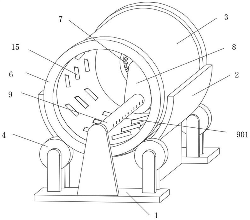
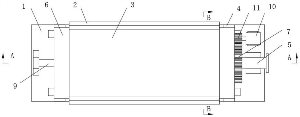
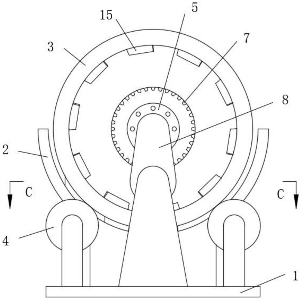
[0023] see Figure 1-7 , a microfiltration machine for solid-liquid separation, comprising a base 1, a waterproof board 2 is fixedly installed on the top of the middle part of the base 1, a water tank 201 is provided at the bottom of the waterproof board 2, and support rollers 4 are movable on the top of the two ends of the base 1. The top of the wheel 4 is fixedly installed with a filter cartridge 3, and the two ends of the filter cartridge 3 are fixedly inst...


PUM


Abstract

The invention relates to the technical field of environmental protection equipment, and discloses a microfiltration machine for solid-liquid separation, which includes a base, a waterproof board is fixedly installed on the top of the middle part of the base, a water tank is provided at the bottom of the waterproof board, and brackets are movable on the top of both ends of the base. The top of the supporting wheel is fixedly equipped with a filter cartridge, and the two ends of the filter cartridge are fixedly installed with rotating rings suitable for the supporting wheel. The middle part of the back of the filter cartridge is provided with a feeding pipe extending into it. The back of the filter cartridge A large ring gear is fixedly installed, and a motor is fixedly installed on the top of the back of the base. The output end of the motor is fixedly connected with a pinion gear meshed with the large ring gear. The front of the box is fixedly connected with a support shaft, and the feeding runner is installed inside the feeding box and driven to rotate through the transmission gear, and the rotating shaft is set to rotate with the feeding runner, which can improve the filtration efficiency and the service life of the filter cartridge .

Description

technical field [0001] The invention relates to the technical field of environmental protection equipment, in particular to a microfilter for solid-liquid separation. Background technique [0002] Solid-liquid separation is often required in environmental protection treatment. For the nature of solid-liquid, the method of filtration is the most direct and effective, and is also the most commonly used. The existing solid-liquid separation equipment includes filter presses, microfilters, etc., among which microfiltration The filter adopts the drum method to transfer the mixed material entering the filter cartridge at one end, and finally discharges the filter residue from the other end to complete the filtration and separation. Its structure is simple and easy to use, but it will also cause some problems: [0003] 1. The microfilter needs to backwash the filter cartridge frequently, so as to realize the clogging and cleaning of the filter layer, but in practice, the clogging o...

Claims


Application Information

Patent Timeline
Patent Type & Authority Patents(China)
IPC IPC(8): B01D33/11B01D33/48B01D33/76
CPCB01D33/11B01D33/76B01D33/48
Inventor 不公告发明人
Owner 深圳市树立水处理设备有限公司
Why Eureka
Try Eureka