POGOPIN probe elasticity test equipment

A technology of elastic testing and probe, which is applied in the field of POGOPIN probe elastic testing equipment, can solve the problems of wasting a lot of time and effort, and achieve the effect of convenient placement or taking, and convenient removal

Active Publication Date: 2022-03-08
鹰潭市云探电子科技有限公司
View PDF10 Cites 3 Cited by
  • Summary
  • Abstract
  • Description
  • Claims
  • Application Information

AI Technical Summary

Problems solved by technology

[0004] In order to overcome the shortcomings of wasting a lot of time and effort to manually press the platen by hand, the purpose of this invention is to provide a time-saving and labor-saving POGOPIN probe elasticity testing equipment

Method used


Image

  • POGOPIN probe elasticity test equipment
  • POGOPIN probe elasticity test equipment
  • POGOPIN probe elasticity test equipment

Examples


Embodiment 1

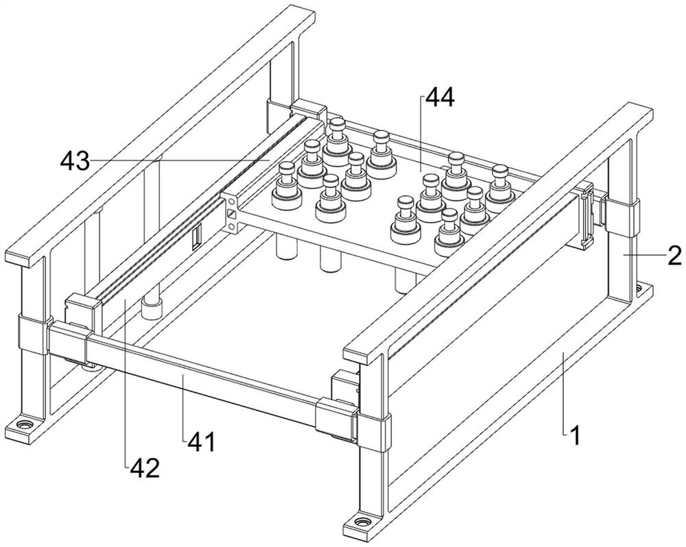
[0035] A kind of POGOPIN probe elasticity testing equipment, refer to Figure 1-Figure 10 , including a base 1, a fixed frame 2, a pressure plate 3, a placement mechanism 4, a displacement mechanism 5, an extrusion mechanism 6 and a limit mechanism 7, the tops of the base 1 on the left and right sides are welded with a fixed frame 2, and the middle part of the fixed frame 2 There is a placement mechanism 4 between them, a displacement mechanism 5 is arranged on the placement mechanism 4, an extruding mechanism 6 is arranged on the top of the base 1, and a pressing plate 3 is arranged on the extruding mechanism 6, and the POGOPIN probe can be moved when the pressing plate 3 moves downward. Squeeze, place mechanism 4 is provided with limit mechanism 7.

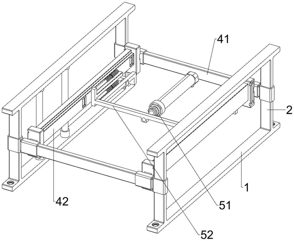
[0036] refer to figure 1 and figure 2 , the placement mechanism 4 includes a fixed rod 41, a slide rail 42, a sliding block 43 and a placement plate 44, a fixed rod 41 is welded symmetrically front and back between the middle...

Embodiment 2

[0042] On the basis of embodiment 1, refer to figure 1 , Figure 11 , Figure 12 and Figure 13 , also includes a stabilizing mechanism 8, the stabilizing mechanism 8 includes a block 82 and a fifth spring 83, the inner middle part of the slide rail 42 is provided with a card slot 81, and the left and right sides of the rear part of the placement plate 44 are all slidably provided with a card. Block 82, the block 82 is connected with the adjacent first guide sleeve 63 slidingly, when the block 82 moves to the outside, it can block the slot 81, thereby stably placing the position of the plate 44, the inside of the block 82 and the placement Fifth springs 83 are provided between the plates 44 .

[0043] Initially, the fifth spring 83 is in a compressed state. When the placing plate 44 moves forward, it drives the block 82 to move forward. The outside movement makes the blocks 82 all be stuck in the slots 81, thereby stabilizing the position of the placement plate 44, making ...


PUM


Abstract

The invention relates to a probe elasticity testing device, in particular to a POGOPIN probe elasticity testing device. The invention aims to provide the POGOPIN probe elasticity testing equipment which is time-saving and labor-saving. The POGOPIN probe elasticity testing equipment comprises bases, fixing frames, a placement mechanism, a displacement mechanism, an extrusion mechanism and the like, the fixing frames are arranged on the tops of the bases on the left side and the right side, the placement mechanism used for fixing a POGOPIN probe is arranged between the middles of the fixing frames, the displacement mechanism used for driving the placement mechanism to move is arranged on the placement mechanism, and the extrusion mechanism is arranged on the left side and the right side of the base. An extrusion mechanism is arranged at the top of the base. A plurality of POGOPIN probes can be supported through the placing plate, then the electric push rod is used as a driving force to drive the connecting rod and the first ejector rod to move backwards so as to drive the first sliding block to move backwards, the first sliding block can drive the pressing plate to move downwards to extrude the POGOPIN probes, the pressing plate does not need to be manually pressed, and time and labor are saved.

Description

technical field [0001] The invention relates to a probe elasticity test equipment, in particular to a POGOPIN probe elasticity test equipment. Background technique [0002] POGOPIN is a very fine probe, which is generally used in precision connections in mobile phones, communications, automobiles, medical, aerospace and other electronic products, which can improve the corrosion resistance, stability and durability of these connectors. [0003] At present, people generally place multiple POGOPIN probes vertically on the same fixed device, then press the top of the POGOPIN probes with a pressure plate, so that the spring in the POGOPIN probes is compressed, and then stand for a period of time, and then The pressure plate is removed, and people can observe the reset situation of the POGOPIN probe at this time, so as to know whether the POGOPIN probe is qualified. A time-saving and labor-saving POGOPIN probe elasticity testing equipment. Contents of the invention [0004] In...

Claims


Application Information

Patent Timeline
Patent Type & Authority Applications(China)
IPC IPC(8): B07C5/02B07C5/34B07C5/36
CPCB07C5/02B07C5/362B07C5/34
Inventor 虞新剑孙建文李恋
Owner 鹰潭市云探电子科技有限公司
Why Eureka
Try Eureka