Power machine room monitoring system

A monitoring system and computer room technology, which is applied in the parts, televisions, electrical components and other directions of the TV system, can solve the problems of inability to collect facial information, monitor dead corners, and difficult security monitoring in the computer room, so as to avoid adverse effects of monitoring.

Pending Publication Date: 2022-03-08
CHINA SOUTHERN POWER GRID DIGITAL GRID RES INST CO LTD
View PDF19 Cites 1 Cited by
  • Summary
  • Abstract
  • Description
  • Claims
  • Application Information

AI Technical Summary

Problems solved by technology

[0003] At present, when the staff installs the monitoring camera in the electric machine room, in order to expand the irradiation area of ​​the monitoring camera, they often install the camera at the corner of the top of the machine room. This installation method can achieve a certain security monitoring effect in ordinary rooms. However, since there are multiple sets of power cabinets inside the power room, and the height of the power cabinets is generally high, when someone breaks in illegally, the camera located in the corner looks down and shoots and cannot effectively collect the facial information of the illegal intruder. Since there are multiple sets of power chassis in the computer room, there will be monitoring dead angles, which brings certain difficulties to the security monitoring of the computer room.

Method used


Image

  • Power machine room monitoring system
  • Power machine room monitoring system
  • Power machine room monitoring system

Examples


Embodiment 1

[0036] According to an embodiment of the present invention,

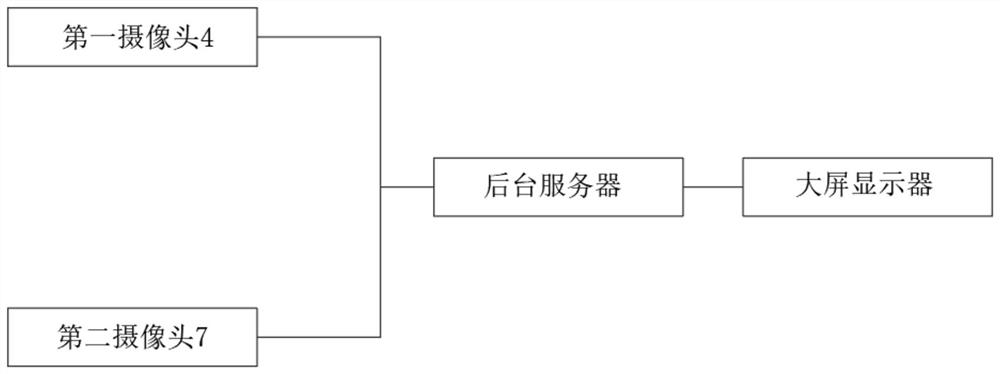
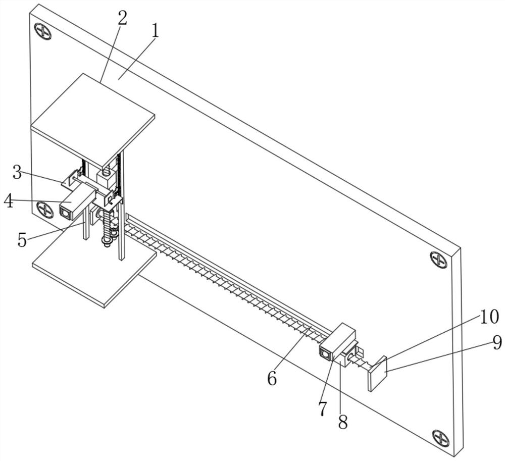
[0037] see Figure 1-10 , a monitoring system for an electric machine room, comprising a mounting plate 1, a positioning hole is provided on one side of the outer wall of the mounting plate 1, the number of the positioning holes is four groups, and the four groups of positioning holes are respectively located on the mounting plate 1 At the four corners of the four positioning holes, fixing bolts are plugged inside the four positioning holes, a horizontal plate 2 is fixedly connected to one side of the outer wall of the mounting plate 1, and a lifting assembly is fixedly connected to the bottom outer wall of the horizontal plate 2, so One side of the lifting assembly is fixedly connected with a first fixed plate 3, the top of the first fixed plate 3 is provided with a rotating assembly, one side of the rotating assembly is fixedly connected with a first camera 4, the mounting plate 1 One side is provided with an adj...

Embodiment 2

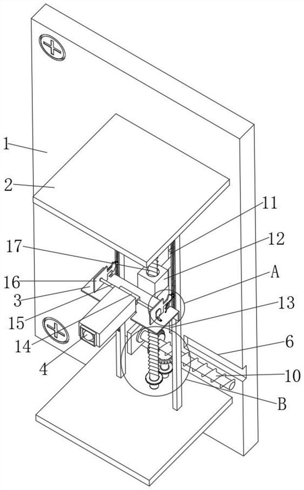
[0039] see Figure 4-7 , the lifting assembly includes a first motor 30 fixedly connected to the outer wall of the bottom of the horizontal plate 2, one end of the output shaft of the first motor 30 is fixedly connected with a second threaded screw 17, and the second threaded screw 17 The peripheral outer wall of the second threaded sleeve 12 is threadedly connected, the first fixing plate 3 is fixedly connected on one side outer wall of the second threaded sleeve 12, and the one side outer wall of the mounting plate 1 is fixedly connected with a fixed Frame 31, one side of the outer wall of the fixed frame 31 is fixedly connected with a slanting rod, the end of the slanted rod away from the fixed frame 31 forms a fixed connection with the first motor 30, and one side of the outer wall of the mounting plate 1 A second chute 13 is provided, the inner walls of both sides of the second chute 13 are slidably connected with the first slider 11, and the outer wall of one side of the...

Embodiment 3

[0041] see Figure 4 , 6 , the rotating assembly includes a support plate 24 fixedly connected to the top outer wall of the first fixed plate 3, and a third fixed plate 16 is rotatably connected to one side of the outer wall of the support plate 24, and the third fixed plate 16 includes a rectangular part and fan-shaped part, the number of the rectangular part is two groups, one side outer wall of the horizontal plate 2 is fixedly connected with a support rod 5, and one side outer wall of the support rod 5 is provided with a second alveolar 21, the The top of the first fixed plate 3 is provided with a guide assembly, and the peripheral outer wall of the fan-shaped portion is provided with a first tooth groove 19, and the first tooth groove 19 is engaged with the guide assembly, and the guide assembly and the first tooth groove 19 are engaged with each other. The two tooth grooves 21 are meshed with each other, and the outer wall of one side of the third fixed plate 16 is fixe...


PUM


Abstract

A power machine room monitoring system disclosed by the present invention comprises a mounting plate, the outer wall of one side of the mounting plate is provided with four groups of positioning holes, the four groups of positioning holes are respectively located at the four corners of the mounting plate, and the four positioning holes are internally inserted with fixing bolts. A transverse plate is fixedly connected to the outer wall of one side of the mounting plate, a lifting assembly is fixedly connected to the outer wall of the bottom of the transverse plate, a first fixing plate is fixedly connected to one side of the lifting assembly, and a rotating assembly is arranged at the top of the first fixing plate. A third fixing plate can drive a first camera to adjust the shooting angle, when a first motor stops rotating, the shooting angle of the first camera is horizontal shooting, the shooting angle of the first camera from top to bottom is changed from top-down shooting to horizontal shooting, overall and face shooting of a person can be effectively carried out, and the shooting efficiency of the person is improved. And the condition of unfavorable monitoring caused by unclear shooting is avoided.

Description

technical field [0001] The invention relates to the field of electric machine room monitoring, in particular to an electric machine room monitoring system. Background technique [0002] The security monitoring system uses optical fiber, coaxial cable or microwave to transmit video signals in its closed loop, and forms an independent and complete system from camera to image display and recording. It can reflect the monitored object in real time, vividly and truly, not only greatly extending the observation distance of the human eye, but also expanding the function of the human eye. It can replace manual monitoring for a long time in harsh environments, allowing people to see Everything that actually happened at the monitored site was recorded by a video recorder. [0003] At present, when the staff installs the monitoring camera in the electric machine room, in order to expand the irradiation area of ​​the monitoring camera, they often install the camera at the corner of the...

Claims


Application Information

Patent Timeline
Patent Type & Authority Applications(China)
IPC IPC(8): F16M11/10F16M11/08F16M11/04F16M11/18H04N5/225
CPCF16M11/10F16M11/08F16M11/043F16M11/18H04N23/50
Inventor 陈晓江黄宏聪梁志宏
Owner CHINA SOUTHERN POWER GRID DIGITAL GRID RES INST CO LTD
Why Eureka
Try Eureka