
Rail transit auxiliary power supply testing device

An auxiliary power supply and rail transit technology, applied in the field of rail transit, can solve the problems of easy electric shock, time-consuming and laborious, and reduce the working efficiency of the test device, so as to achieve the effect of improving safety and improving work efficiency

Pending Publication Date: 2022-03-08
SHENZHEN CHANGLONG RAILWAY ELECTRONICS ENGCO
View PDF0 Cites 1 Cited by
  • Summary
  • Abstract
  • Description
  • Claims
  • Application Information

AI Technical Summary

Problems solved by technology

[0003] The existing rail transit auxiliary power supply test device uses the auxiliary power supply to be directly electrically connected to the load module, so as to detect the state of the auxiliary power supply under different load conditions, thereby judging the actual status of the auxiliary power supply; Under different load conditions, it needs to be electrically connected to different load modules, which requires repeated wiring and connection between the auxiliary power supply and the load module, which is time-consuming and laborious, reduces the working efficiency of the test device, and is prone to accidents such as electric shock

Method used


Image

  • Rail transit auxiliary power supply testing device
  • Rail transit auxiliary power supply testing device
  • Rail transit auxiliary power supply testing device

Examples


Embodiment Construction

[0032] In order to make the object, technical solution and advantages of the present invention clearer, the present invention will be further described in detail below in conjunction with the accompanying drawings and embodiments. It should be understood that the specific embodiments described here are only used to explain the present invention, not to limit the present invention.

[0033] The specific implementation of the present invention will be described in detail below in conjunction with specific embodiments.

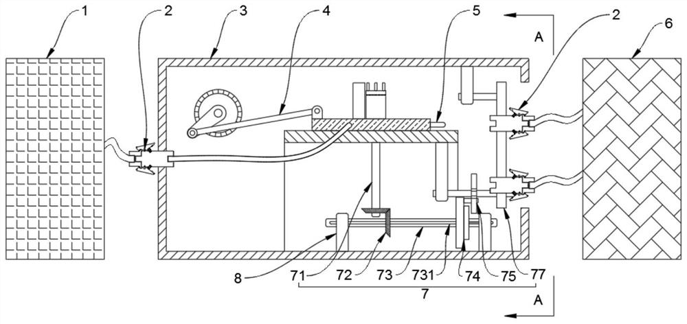
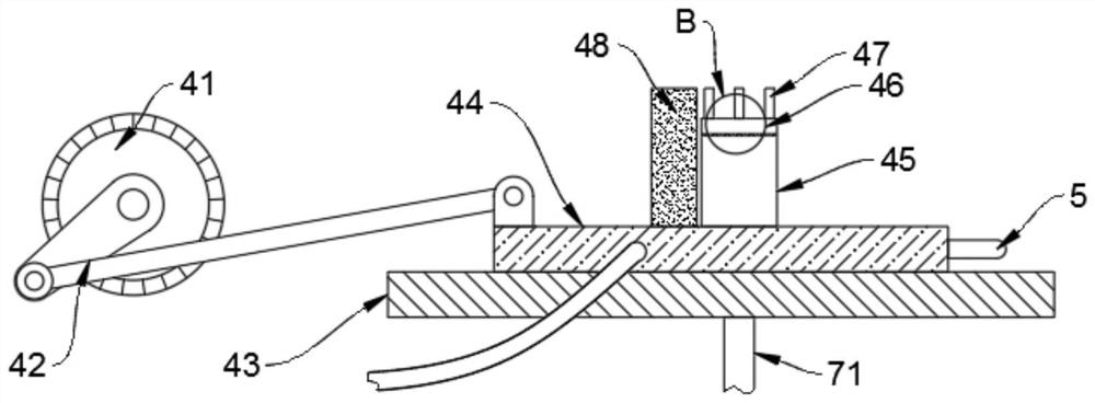
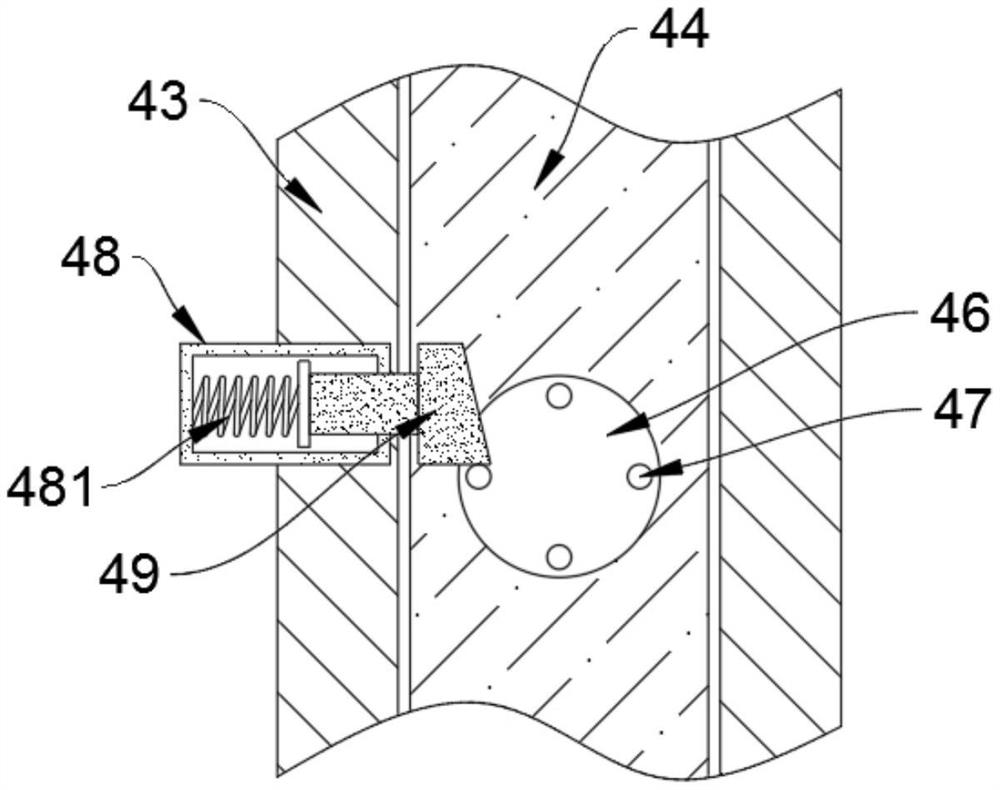
[0034] Such as Figures 1 to 8 As shown, a rail transit auxiliary power supply test device provided as an embodiment of the present invention includes a transfer box 3, and the transfer box 3 is used to transfer the auxiliary power supply 1 and the load module 6. The transfer One side of the box 3 is provided with a transfer interface 31, and the other end of the transfer box 3 is provided with a wiring mechanism 2, and the wiring mechanism 2 is used for electri...


PUM


Abstract

The invention is applicable to the technical field of rail transit, and provides a rail transit auxiliary power supply test device, which comprises a transfer box and further comprises a connecting mechanism, the connecting mechanism comprises a driving part, a rotating module, a sliding seat, a sliding part, a fixed seat, a rotating seat, a rotating part and a steering part, and one end of the sliding part is provided with a contact; and the switching mechanism comprises a connecting shaft, a transmission module, a transmission shaft, a first rotating disc, a second rotating disc, a rotating shaft and a rotating belt, and the transmission belt is provided with a plurality of wiring mechanisms used for electrically connecting the contact and the load module. According to the rail transit auxiliary power source test device, the auxiliary power source is electrically connected with the contact through the wiring mechanism, the contact is electrically connected with the wiring mechanism installed on the transmission belt through the connecting mechanism, the contact is electrically connected with different load modules, and then the auxiliary power source is electrically connected with the different load modules. The working efficiency of the test device is improved, and the safety of the device is improved.

Description

technical field [0001] The invention belongs to the technical field of rail transit, and in particular relates to a rail transit auxiliary power supply test device. Background technique [0002] Rail transit refers to a type of vehicle or transportation system that operating vehicles need to run on a specific track. The most typical rail transit is a railway system composed of traditional trains and standard railways. Auxiliary power supply for rail transit refers to the device that generates electric energy on rail transit and provides electric energy for electrical components of rail transit for maintenance, testing and lighting. Before the auxiliary power supply of rail transit is used, a power supply test is required to ensure the normal use of the auxiliary power supply. [0003] The existing rail transit auxiliary power supply test device uses the auxiliary power supply to be directly electrically connected to the load module, so as to detect the state of the auxiliar...

Claims


Application Information

Patent Timeline
IPC IPC(8): G01R31/40G01R1/04
CPCG01R31/40G01R1/0416
Inventor 周波房甜甜周坤谢智恩张景福王玥张艳玲
Owner SHENZHEN CHANGLONG RAILWAY ELECTRONICS ENGCO
Learn More