Relay protection data monitoring equipment and processing system in power supply network

A technology for protecting data and power supply networks, applied in information technology support systems, emergency protection circuit devices, electrical components, etc., can solve problems such as remote control, complicated on-site wiring, confusion, etc., to assist the neat layout of lines and facilitate maintenance , The effect of timely protection circuit

Active Publication Date: 2022-03-08
JUXIAN POWER SUPPLY CO STATE GRID SHANDONG ELECTRIC POWER CO
View PDF8 Cites 0 Cited by
  • Summary
  • Abstract
  • Description
  • Claims
  • Application Information

AI Technical Summary

Problems solved by technology

[0003] However, in the prior art, the relay protection method is single, and the configuration of the input quantity is required in advance. It has limitations in the application of complex circuits. It is often used in conjunction with the relay monitor for on-site testing, and the monitor is temporarily connected during use, which is quite inconvenient. Moreover, continuous circuit detection cannot be guaranteed, and the data monitoring in the interface cannot be continuously carried out, and remote control cannot be performed. In addition, during the wiring process, the complicated wiring also makes the on-site wiring confusing, which is not conducive to circuit maintenance.

Method used


Image

  • Relay protection data monitoring equipment and processing system in power supply network
  • Relay protection data monitoring equipment and processing system in power supply network
  • Relay protection data monitoring equipment and processing system in power supply network

Examples


Embodiment Construction

[0029] The following description serves to disclose the present invention to enable those skilled in the art to carry out the present invention. The preferred embodiments described below are only examples, and those skilled in the art can devise other obvious variations.

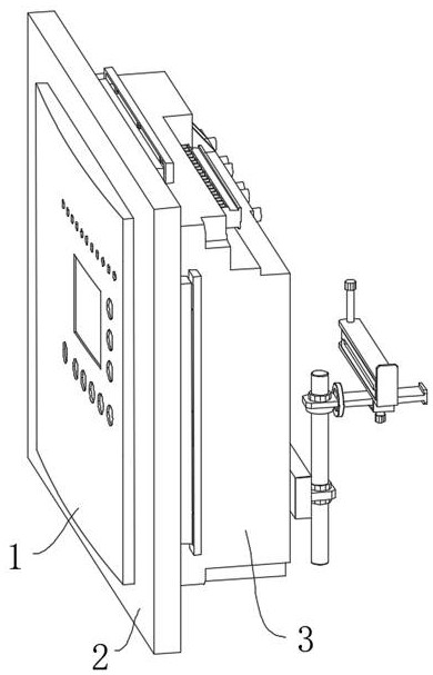
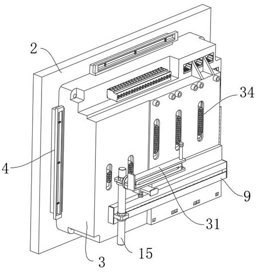
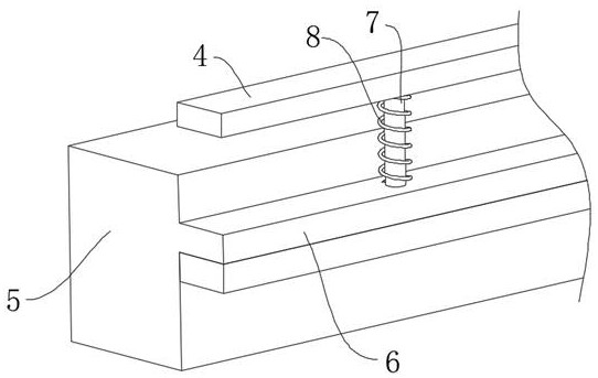
[0030] Such as Figure 1-Figure 8 The relay protection data monitoring equipment in the power supply network shown includes a relay monitor main body 3, a front plate 2 is fixedly installed at the front end of the relay monitor main body 3, and the upper, lower and both sides of the relay monitor main body 3 The outer surface is provided with a clamping mechanism, the clamping mechanism is located at the rear of the front plate 2, the rear end surface of the main body 3 of the relay monitor is fixedly installed with guide rails 9 extending along both sides, and the rear end of the guide rail 9 slides and is equipped with a slide plate 10. The inner side of the slide plate 10 and the guide rail 9 is position...


PUM


Abstract

The invention relates to the technical field of circuit protection, in particular to relay protection data monitoring equipment in a power supply network, which comprises a relay monitor main body, a front plate is fixedly mounted at the front end of the relay monitor main body, and clamping mechanisms are arranged on the outer surfaces of the upper, lower and two sides of the relay monitor main body. The clamping mechanism is located behind the front plate, guide rails extending in the two side directions are fixedly installed on the rear end face of the relay monitor body, a sliding plate is slidably installed at the rear ends of the guide rails in a clamped mode, and the sliding plate and the inner sides of the guide rails are positioned through a meshing mechanism. The device can be rapidly and conveniently installed on the power distribution cabinet, has a wiring assisting function, does not cause the problem of disordered wires in the power distribution cabinet, achieves the data monitoring of the relay and the control of a relay circuit, and can control the circuit to be disconnected when abnormal circuit data is detected, thereby achieving the effect of protecting the circuit in time.

Description

technical field [0001] The invention relates to the technical field of circuit protection, in particular to a monitoring device and a processing system for relay protection data in a power supply network. Background technique [0002] The relay is an electric control device, which is an electrical appliance that causes the controlled quantity to undergo a predetermined step change in the electrical output circuit when the change of the input quantity (excitation quantity) meets the specified requirements. It has an interactive relationship between the control system (also known as the input loop) and the controlled system (also known as the output loop). Usually used in automatic control circuits, it is actually an "automatic switch" that uses small currents to control large current operations, so it plays the role of automatic adjustment, safety protection, conversion circuits, etc. in the circuit, that is, it is used in power supply Circuit protection monitoring equipment...

Claims


Application Information

Patent Timeline
Patent Type & Authority Applications(China)
IPC IPC(8): H02J13/00H02B1/24H02B1/20H02B1/32H02H7/26
CPCH02J13/00002H02J13/00006H02J13/00032H02B1/24H02B1/202H02B1/32H02H7/26Y02E60/00Y04S10/20Y04S40/12
Inventor 李昊东王骏平董文斌梁玲玲孙晓飞周升强刘智琳卢衍春王星赫
Owner JUXIAN POWER SUPPLY CO STATE GRID SHANDONG ELECTRIC POWER CO
Why Eureka
Try Eureka