Photographing system and diagnosis method thereof

A diagnostic method and system failure technology, applied in the field of vehicle driving, can solve problems such as misjudgment, difficulty in timely replacement of timing methods, and impact on the service life of the camera module, etc., to achieve the effect of improving diagnostic efficiency

Pending Publication Date: 2022-03-08
QISDA SUZHOU +1
View PDF0 Cites 0 Cited by
  • Summary
  • Abstract
  • Description
  • Claims
  • Application Information

AI Technical Summary

Problems solved by technology

The camera module itself has a certain service life. Due to the large changes in the application environment of the car, the application in different weather and environments will affect the real service life of the camera module, and it is not easy to replace it in time through a simple timing method.
Once there is a problem with the camera module, for example, it cannot be turned on, or it freezes on a certain screen light, the system may conduct calculations and analysis on the wrong information obtained from the camera module, and make a wrong judgment, which may endanger the lives of vehicle passengers and passers-by.

Method used


Image

  • Photographing system and diagnosis method thereof
  • Photographing system and diagnosis method thereof
  • Photographing system and diagnosis method thereof

Examples


no. 1 example

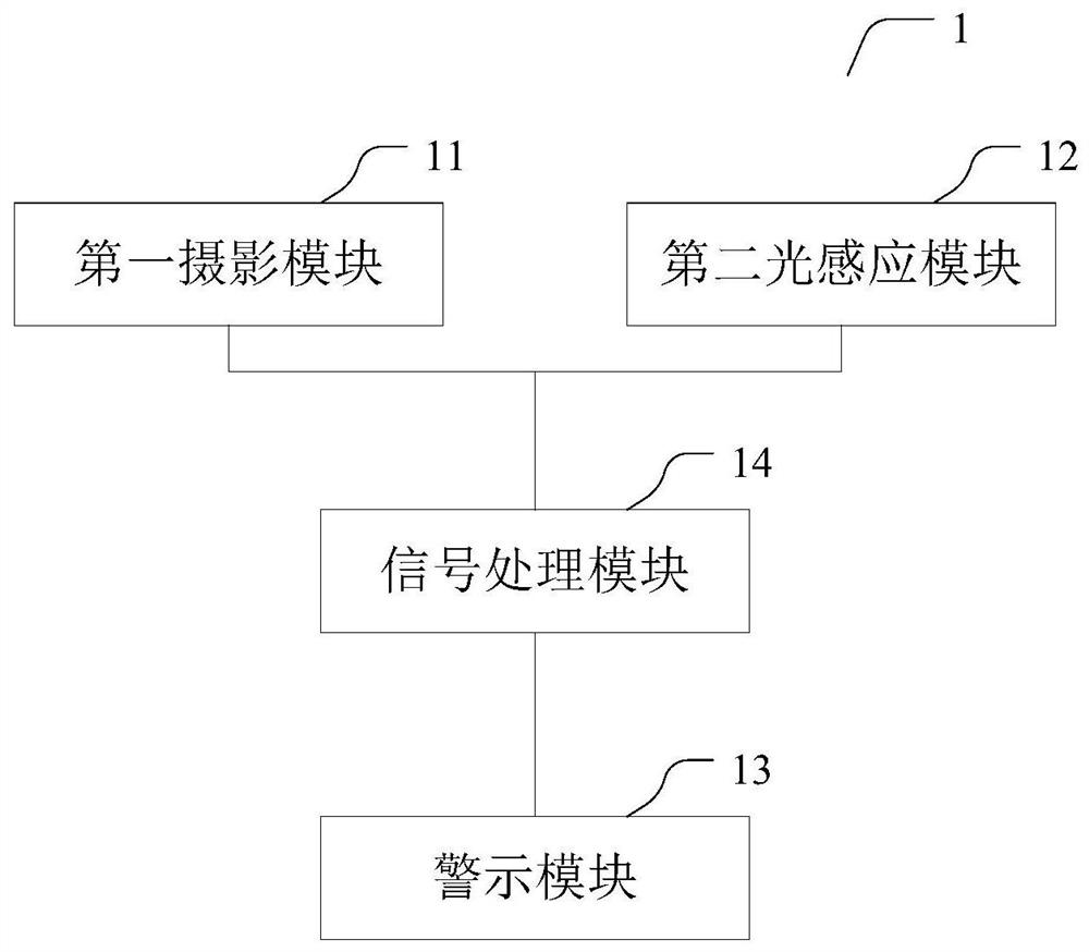
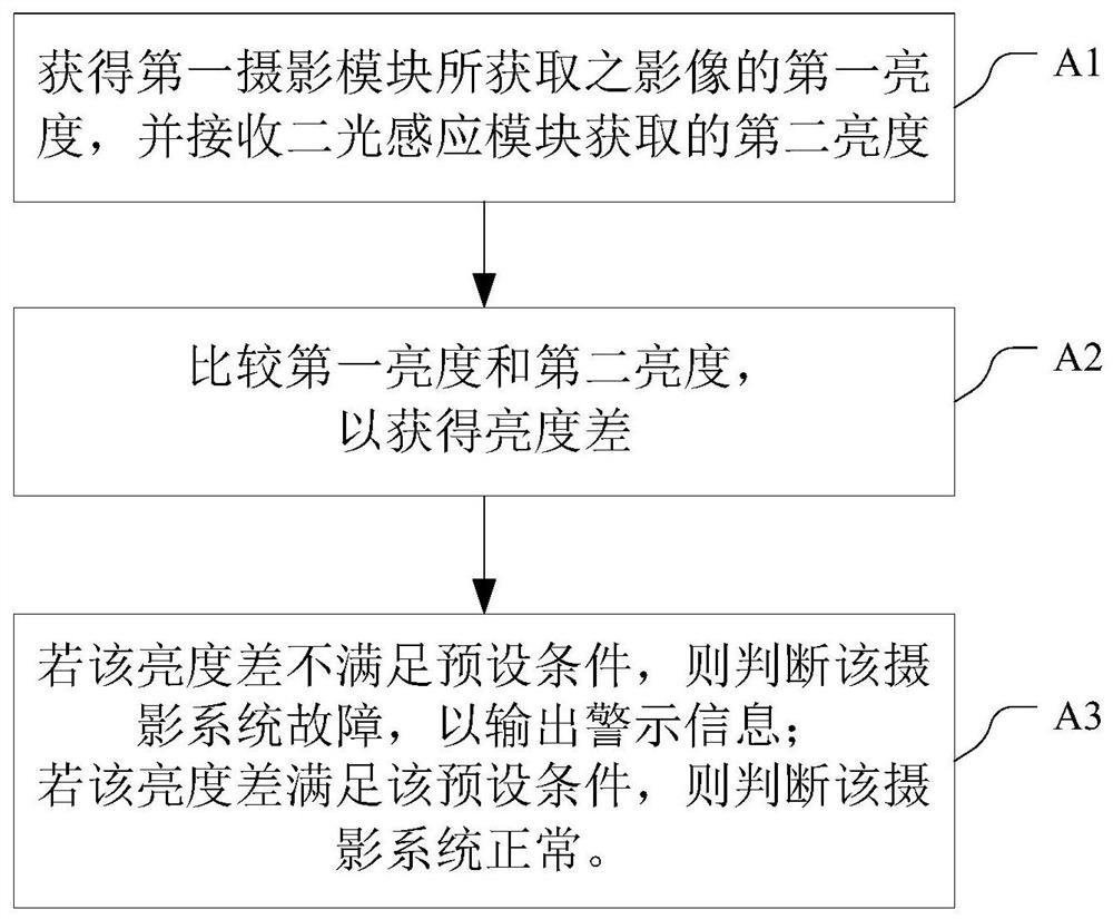
[0050] Please refer to figure 1 with figure 2 , figure 1 It is a schematic structural diagram of a photography system 1 provided in the first embodiment of the present invention, figure 2 It is a schematic diagram of the diagnosis process of the imaging system 1 in this embodiment. The camera system 1 at least includes a first camera module 11 , a second light sensing module 12 , a warning module 13 and a signal processing module 14 . Wherein, the first camera module 11 is the main input module of the camera system 1 , and is used for acquiring images within its field of view. The second light sensing module 12 is used for sensing ambient light. The warning module 13 is used to output warning information. The signal processing module 14 is coupled to the first photographing module 11, the second light sensing module 12 and the warning module 13, and the signal processing module 14 is used to judge the photographing according to the brightness difference sensed by the fi...

no. 2 example

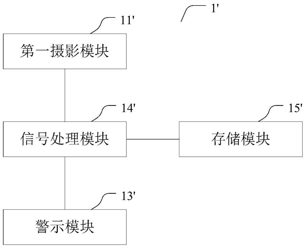
[0071] Please refer to image 3 with Figure 5 , image 3 A photography system 1' provided for the second embodiment of the present invention, Figure 5 It is a diagnostic method of the imaging system 1' in this embodiment. The camera system 1' at least includes a first camera module 11', a warning module 13', a data processing module 14' and a storage module 15'. The structure of the photographing system 1' is roughly the same as that of the photographing system 1, so the photographing system 1' basically uses the component numbers of the photographing system 1, wherein the functions and descriptions of the modules refer to the corresponding functional modules in the first embodiment, and are not described here. Again, only part of the content of the second embodiment that differs from the first embodiment is described below. The first camera module 11' is the main input module of the camera system 1', which is used to acquire images within its field of view. The warning...

no. 3 example

[0083] Image 6 It is a schematic diagram of the diagnosis flow of the imaging system in the third embodiment of the present invention. The camera system is set in the vehicle, and the camera system includes a first camera module.

[0084] S0. In response to starting or waking up the vehicle, go to step S1.


PUM


Abstract

The invention discloses a diagnostic method of a photographing system, which comprises the following steps of: A1, acquiring first brightness of an image acquired by a first photographing module, and receiving second brightness acquired by a second light sensing module; a2, comparing the first brightness with the second brightness to obtain a brightness difference; and A3, if the brightness difference does not meet a preset condition, judging that the photographing system fails to output warning information. And if the brightness difference meets the preset condition, judging that the photographing system is normal. Compared with the prior art, the brightness value is synchronously sensed through the light sensing module matched with the photographing module, and whether the photographing module breaks down or not is judged according to the difference of the brightness values of the light sensing module and the photographing module. The photoinduction module and the photographing module are different in cost and service life, so that the photographing module can be diagnosed with low cost by adopting the photoinduction module.

Description

technical field [0001] The invention relates to a photography system and a diagnosis method thereof, in particular to a diagnosis method of a photography system applied in the field of vehicle driving. Background technique [0002] With the rise and development of car assisted driving or car autopilot, from simple reversing images, driving recorders, to complex surround view image systems, and even autopilot systems related to car safety, the application of photography systems is increasing to a pivotal role. The lens of the photography system is like the human eye, capturing image information and providing it to the processor for various applications. Now, the number of camera modules configured on a car has reached 4 to 6. [0003] The stability of camera systems is becoming more and more important as the use of camera systems in cars grows and we rely more and more on them. The camera module itself has a certain service life. Due to the large changes in the application...

Claims


Application Information

Patent Timeline
IPC IPC(8): H04N17/00
CPCH04N17/002
Inventor 张智明
Owner QISDA SUZHOU
Why Eureka
Try Eureka