Cam sliding type variable valve lift system, engine and vehicle

A valve lift and sliding technology, which is applied in the direction of engine components, machines/engines, mechanical equipment, etc., can solve the problem of large relative ratio of the quality switching window of the cam slipper, high tolerance control requirements, high inertia and speed of the cam slipper, etc. problems, to achieve the effect of reducing production costs and failure risks, reducing the difficulty of tolerance control, and reducing production costs

Pending Publication Date: 2022-03-11
CHONGQING CHANGAN AUTOMOBILE CO LTD
View PDF1 Cites 0 Cited by
  • Summary
  • Abstract
  • Description
  • Claims
  • Application Information

AI Technical Summary

Problems solved by technology

[0005] The object of the present invention is to provide a cam sliding variable valve lift system, an engine and a vehicle to solve the problem that the existing sliding camshaft has a large number of components, so that the tolerance control requirements between the components are high, and there are production problems. The problem of high cost, and the use of integral cam sliding sleeves, the relative ratio of the mass of the cam sliding sleeves to the switching window is large, resulting in high inertia and speed of the cam sliding sleeves, and only relying on the steel ball + spring mechanism to stop, it will happen Large displacement fluctuations, so there is a problem of failure

Method used

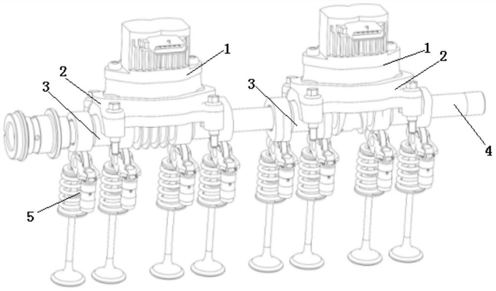
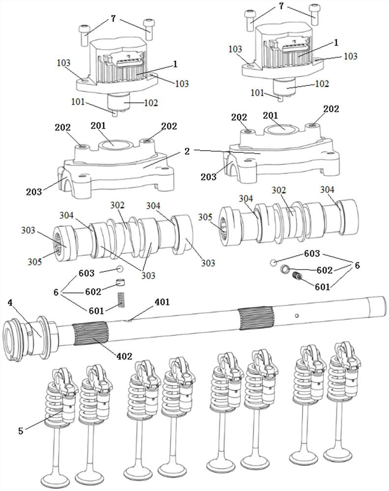
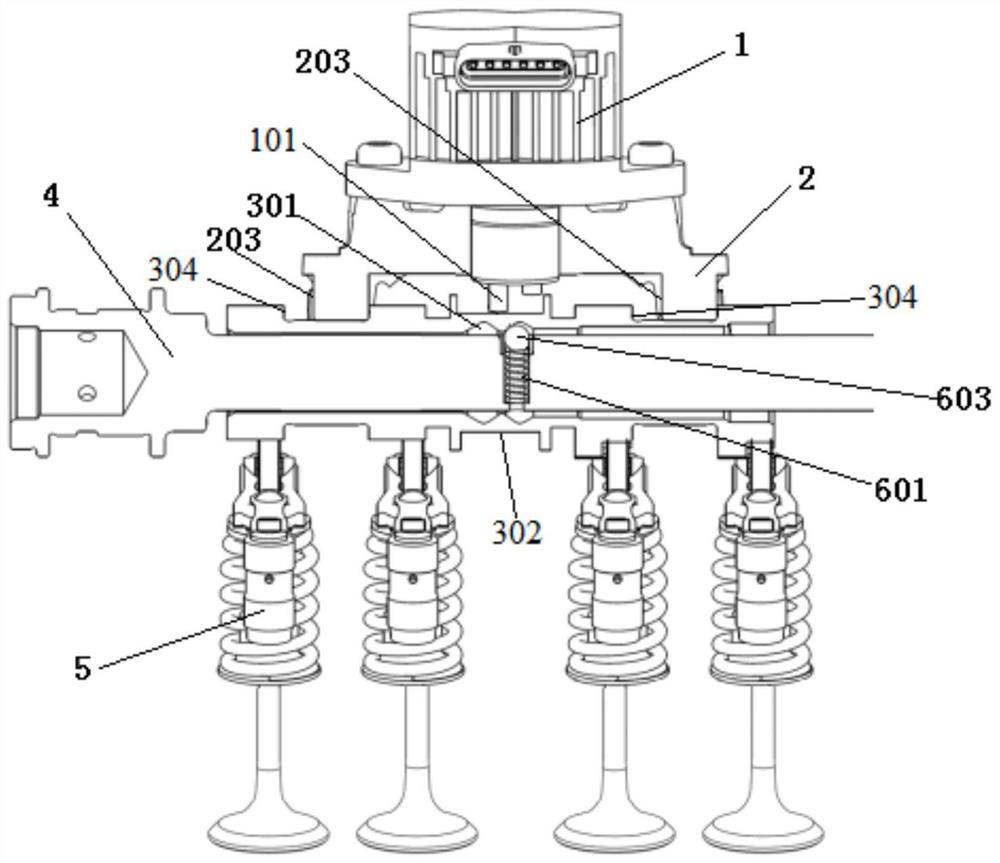

Image

  • Cam sliding type variable valve lift system, engine and vehicle
  • Cam sliding type variable valve lift system, engine and vehicle
  • Cam sliding type variable valve lift system, engine and vehicle

Examples


Embodiment Construction

[0029] Embodiments of the present invention will be described below with reference to the accompanying drawings and preferred embodiments, and those skilled in the art can easily understand other advantages and effects of the present invention from the content disclosed in this specification. The present invention can also be implemented or applied through other different specific implementation modes, and various modifications or changes can be made to the details in this specification based on different viewpoints and applications without departing from the spirit of the present invention. It should be understood that the preferred embodiments are only for illustrating the present invention, but not for limiting the protection scope of the present invention.

[0030] It should be noted that the diagrams provided in the following embodiments are only schematically illustrating the basic ideas of the present invention, and only the components related to the present invention ar...


PUM


Abstract

The invention relates to a cam sliding type variable valve lift system, an engine and a vehicle. The lift system comprises an actuator which is installed on the cam shaft cover and acts on the one-piece cam sliding sleeve. The one-piece cam sliding sleeve is assembled on the cam shaft mandrel, a stop ring groove is formed in the inner wall of the one-piece cam sliding sleeve, the cam shaft mandrel is matched with the stop ring groove through an elastic connecting piece to stop the one-piece cam sliding sleeve, and a switching spiral groove is formed in the outer wall of the one-piece cam sliding sleeve and used for being matched with a pin of an actuator. The one-piece cam sliding sleeve is provided with two groups of cams corresponding to the valve assembly; when the valve lift is switched, the cam shaft mandrel rotates to drive the one-piece cam sliding sleeve to move, the elastic connecting piece moves from one check ring groove to the other check ring groove, and switching of the valve assembly is achieved. The invention provides an engine. The engine comprises a lift system. The invention provides a vehicle including an engine. The problems that an existing sliding type cam shaft is numerous in parts, and the tolerance control requirement between the parts is high are solved.

Description

technical field [0001] The invention relates to the technical field of automobile engines, in particular to a cam sliding variable valve lift system, an engine and a vehicle. Background technique [0002] The Camshaft Sliding Variable Valve Lift System (Camshaft Sliding Variable Valve Lift System) is to make the cam sliding sleeve axially move on the camshaft core shaft during the engine running, so as to realize the cam and roller rocking with different lifts. Arm contact, so that the engine can obtain the best valve lift under operating conditions, thereby improving the fuel economy, power torque and emission characteristics of the engine. [0003] The sliding camshaft in the prior art generally adopts an independent cam sliding sleeve structure for each cylinder, and at the same time, each cylinder is matched with an independent actuator (that is, four cylinders-four actuators), so there are many parts and components. The sleeve only relies on the steel ball + spring mec...

Claims


Application Information

Patent Timeline
Patent Type & Authority Applications(China)
IPC IPC(8): F01L13/00F01L1/047
CPCF01L13/0015F01L1/047F01L2013/0078
Inventor 周敬乔谢宗让林翰
Owner CHONGQING CHANGAN AUTOMOBILE CO LTD
Why Eureka
Try Eureka