Two-position three-way control valve of high-pressure common-rail oil injector

A high-pressure common rail, two-position three-way technology, applied in the direction of fuel injection devices, machines/engines, charging systems, etc., can solve the problem of reducing the life of the injector, affecting the fuel injection rate, reducing the opening and closing speed of the needle valve, etc. problems, to achieve the effect of improving the opening and closing response, increasing the oil supply rate, and reducing the dynamic oil return volume

Active Publication Date: 2022-03-11
SHANGHAI UNIV OF ENG SCI
View PDF8 Cites 0 Cited by
  • Summary
  • Abstract
  • Description
  • Claims
  • Application Information

AI Technical Summary

Problems solved by technology

The solid surface is subjected to repeated impacts of this kind of impact, and the material will fatigue and fall off, thereby forming cavitation, causing fatigue damage, and reducing the life of the injector
At the same time, the diameter of the oil inlet orifice and the oil outlet orifice are small, and it takes a certain time for the pressure difference to form, thus reducing the opening and closing speed of the needle valve, thereby affecting the fuel injection rate

Method used


Image

  • Two-position three-way control valve of high-pressure common-rail oil injector
  • Two-position three-way control valve of high-pressure common-rail oil injector
  • Two-position three-way control valve of high-pressure common-rail oil injector

Examples


Embodiment Construction

[0043] The present invention will be further described below in combination with specific embodiments. It should be understood that these examples are only used to illustrate the present invention and are not intended to limit the scope of the present invention. In addition, it should be understood that after reading the teachings of the present invention, those skilled in the art can make various changes or modifications to the present invention, and these equivalent forms also fall within the scope defined by the appended claims of the present application.

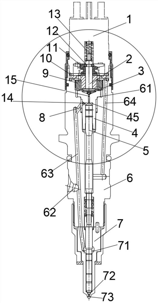
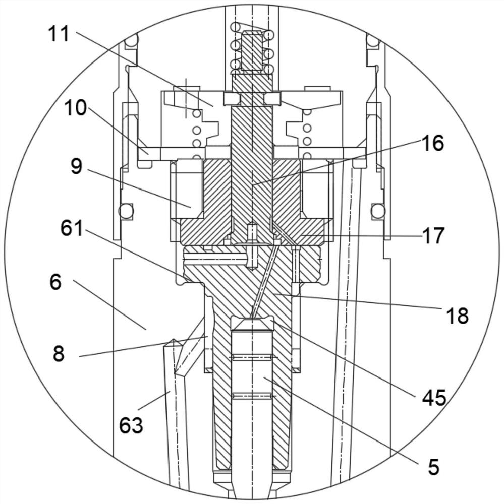
[0044] Such as figure 2 As shown, the high-pressure common rail injector includes an electromagnet, an oil storage chamber 8, a control chamber 45 and a low-pressure oil area;

[0045] High-pressure common rail injector two-position three-way control valve such as figure 2 As shown, including a new control rod 16, a valve seat 17 and a new control sleeve 18;

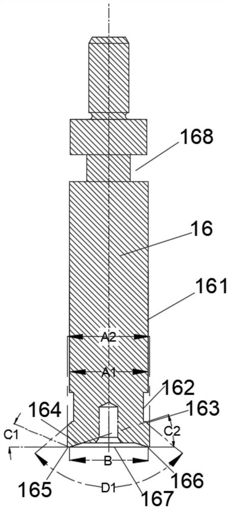
[0046] The complete structure of the new control rod 16 ...


PUM


Abstract

The invention relates to a two-position three-way control valve of a high-pressure common-rail oil injector, the high-pressure common-rail oil injector comprises an electromagnet, an oil storage chamber, a control chamber and a low-pressure oil area, and the two-position three-way control valve comprises a new control rod, a valve seat and a new control sleeve; the valve seat is hollow, and the new control rod is inserted into a hollow hole of the valve seat; the outer circle face of the upper portion of the new control rod is attached to the hole wall face of the upper portion of the hollow hole of the valve seat to form sealing. The lower end face of the valve seat is attached to the upper end face of the new control sleeve to form sealing. A groove is formed in the new control rod, an oil groove is formed in the valve seat, and a central oil drainage hole is formed in the new control sleeve; the groove communicates with the oil storage chamber, the oil groove communicates with the control chamber, and the center oil drainage hole communicates with the low-pressure oil area. The electromagnet is powered on and powered off to drive the new control rod to move at the upper sealing position and the lower sealing position, fuel communication of the groove, the oil groove and the center oil drainage hole is formed, and a two-position three-way valve is formed. The requirement for electromagnetic force is reduced, the opening and closing response of the needle valve is improved, and the oil return amount of the oil injector is reduced.

Description

technical field [0001] The invention belongs to the field of fuel injection systems for internal combustion engines, in particular to a two-position three-way control valve for a pressure balance valve of a high-pressure common rail fuel injector. Background technique [0002] At present, high-pressure common rail injectors use two-position two-way control valves, such as ball valves, see figure 1 , It consists of high-speed electromagnet 1, control rod 2, steel ball 3, control sleeve 4, long valve stem 5, injector body 6, injector nozzle assembly 7, compression nut 9 and armature 11 and other components. The compression nut 9 tightly presses the control sleeve 4 on the shoulder 61 of the injector body 6 . [0003] High-pressure fuel enters from the high-pressure oil inlet hole 62 on the injector body 6 , passes upward through the oil inlet passage 63 , enters the high-pressure oil storage chamber 8 , and then reaches the control chamber 45 through the oil inlet orifice 14 ...

Claims


Application Information

Patent Timeline
IPC IPC(8): F02M47/02F02M63/00
CPCF02M47/027F02M63/0017F02M63/0045
Inventor 郑金保周健缪雪龙王九如
Owner SHANGHAI UNIV OF ENG SCI
Why Eureka
Try Eureka