

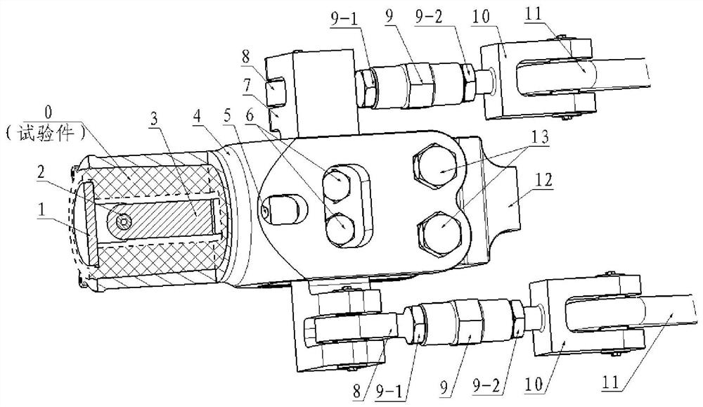
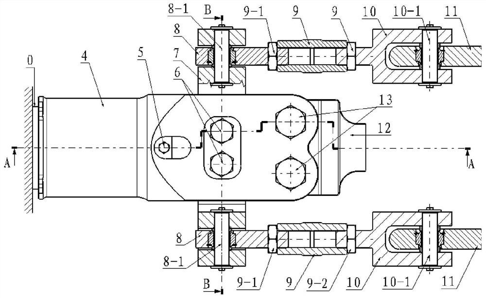
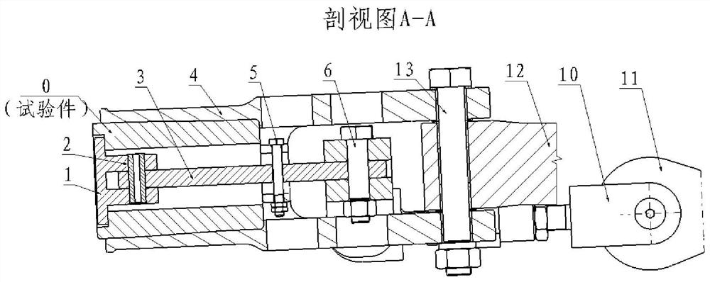
Centrifugal force separation type loading test device for rigid rotor wing main paddle central piece
A loading test device and centrifugal force technology, applied in the testing of mechanical components, testing of machine/structural components, testing the strength of materials by applying stable tension/pressure, etc., can solve the problems of uncontrollable risks, difficulty in test measurement and control, etc. Achieve the effect of high reliability of test data, coordinated structure and stable loading
- Summary
- Abstract
- Description
- Claims
- Application Information
AI Technical Summary
Problems solved by technology
Method used
Image

Examples
Embodiment Construction
[0033] In order to make the purpose, technical solution and advantages of the present invention more clear, the embodiments of the present invention will be described in detail below in conjunction with the accompanying drawings. It should be noted that, in the case of no conflict, the embodiments in the present application and the features in the embodiments can be combined arbitrarily with each other.
[0034] It has been explained in the above-mentioned background technology that the existing scheme of carrying out the fatigue test by centrifugal force end loading, because the centrifugal force unloads the swinging force and the shimmy force load, therefore, it is necessary to greatly increase the swinging force and the shimmy force during the test, so that As a result, it is difficult to measure and control the test, and there are problems of uncontrollable risks.
[0035] In view of the existing solution of fatigue test by centrifugal force end loading, there is a problem...
PUM
 Abstract
Description
Claims
Application Information