
Two-pole deflection magnet borrowing magnetic measurement method

A deflection magnet and magnetic measurement technology, which is applied in the direction of measuring devices, measuring magnetic variables, instruments, etc., can solve the problem of poor accuracy of measurement results, the measurement stroke of the Hall point measuring machine cannot cover the entire magnetic measuring area, and the lengthening of the Hall point measuring machine. Problems such as the travel range of the machine probe rod

Active Publication Date: 2022-05-03
北京高能锐新科技有限责任公司
View PDF0 Cites 0 Cited by
  • Summary
  • Abstract
  • Description
  • Claims
  • Application Information

AI Technical Summary

Problems solved by technology

[0003] This application expects to provide a two-pole deflection magnet borrowing magnetic measurement method to solve the problem that in the prior art, the measuring stroke of the Hall point measuring machine cannot cover the entire magnetic measuring area, and the probe rod travel of the Hall point measuring machine can be lengthened range, resulting in poor measurement accuracy

Method used


Image

  • Two-pole deflection magnet borrowing magnetic measurement method
  • Two-pole deflection magnet borrowing magnetic measurement method
  • Two-pole deflection magnet borrowing magnetic measurement method

Examples


Embodiment Construction

[0027] The application will be further described in detail below in conjunction with the accompanying drawings and embodiments. It should be understood that the specific embodiments described here are only used to explain related inventions, rather than to limit the invention. It should also be noted that, for ease of description, only parts related to the invention are shown in the drawings.

[0028] It should be noted that, in the case of no conflict, the embodiments in the present application and the features in the embodiments can be combined with each other. The present application will be described in detail below with reference to the accompanying drawings and embodiments.

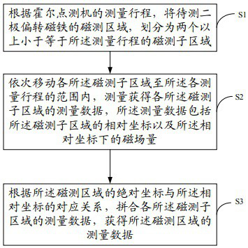
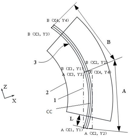
[0029] like figure 1 , figure 2 As shown, the embodiment of the present invention provides a two-pole deflection magnet borrowing magnetic measurement method, including:

[0030] S1: According to the measuring stroke 1 of the Hall point measuring machine, the magnetic measuring area of ​​the tw...


PUM


Abstract

The present application discloses a magnetic measurement method for a two-pole deflection magnet, which includes: according to the measurement stroke of the Hall point measuring machine, dividing the magnetic measurement area of ​​the two-pole deflection magnet to be measured into two or more parts less than or equal to the measurement area The magnetic measurement sub-region of the stroke; move each of the magnetic measurement sub-regions to the range of each measurement stroke in turn, measure and obtain the measurement data of each of the magnetic measurement sub-regions, and the measurement data includes the magnetic measurement sub-region The relative coordinates of the relative coordinates and the magnetic field amount under the relative coordinates; according to the corresponding relationship between the absolute coordinates of the magnetic measurement area and the relative coordinates, the measurement data of each of the magnetic measurement sub-areas is combined to obtain the magnetic field of the magnetic measurement area. Measurement data. The above scheme does not need to lengthen the stroke range of the probe rod of the Hall point measuring machine, so it avoids the problem of poor accuracy of the measurement results caused by the decrease in the running accuracy of the probe rod as its stroke increases; the accuracy of the measurement is guaranteed.

Description

technical field [0001] The invention generally relates to the technical field of magnetic field measurement, and in particular to a magnetic measurement method with a two-pole deflection magnet. Background technique [0002] At present, a Hall point measuring machine is generally used to measure the magnetic field of a magnet. The measuring stroke of the Hall point measuring machine is a long rectangular area. For the two-pole long deflection magnet with small bending radius, the measuring stroke of the existing Hall point measuring machine cannot cover the entire magnetic measuring area. In order to be able to measure smoothly , a current practice is to replace the longer probe rod to lengthen the travel range of the probe rod of the Hall point measuring machine. However, as the travel range of the probe rod increases, the running accuracy of the probe rod decreases accordingly. This will directly affect the accuracy of the measurement results. Contents of the invention ...

Claims


Application Information

Patent Timeline
Patent Type & Authority Patents(China)
IPC IPC(8): G01R33/07G01R33/00
CPCG01R33/07G01R33/0035
Inventor 宋迺斌郭润兵张占军杨丛莱牟智慧
Owner 北京高能锐新科技有限责任公司
Learn More