LED backlight matrix driving circuit and driving voltage detecting and adjusting method thereof

A driving circuit and driving voltage technology, applied in the field of communication, can solve the problems of increasing chip cost, poor flexibility, increasing chip wiring area, etc., and achieve the effect of fast and accurate adjustment

Active Publication Date: 2022-03-11
X-SIGNAL INTEGRATED CO
View PDF5 Cites 1 Cited by
  • Summary
  • Abstract
  • Description
  • Claims
  • Application Information

AI Technical Summary

Problems solved by technology

Since the comparator cannot directly output the voltage value V of the negative terminal of the LED light string led Accurate value, can only output high and low signals, when the voltage needs to be adjusted, the driving voltage V is controlled by the driver chip boost Perform feedback adjustment, increase or decrease the voltage, and adjust repeatedly until the negative terminal voltage value of all LED light string channels is V led The value meets the set value. This debugging method has poor flexibility and takes a long time to adjust.
At the same time, the detection unit in the driver chip uses the comparator circuit design method so that each LED light string channel needs to be connected to three comparators. This circuit structure increases the chip wiring area and increases the chip cost.

Method used


Image

  • LED backlight matrix driving circuit and driving voltage detecting and adjusting method thereof
  • LED backlight matrix driving circuit and driving voltage detecting and adjusting method thereof
  • LED backlight matrix driving circuit and driving voltage detecting and adjusting method thereof

Examples


Embodiment Construction

[0024] In order to make the purpose, technical solution and advantages of the present invention clearer, the following in conjunction with the attached Figure 3-5 The present invention will be described in further detail.

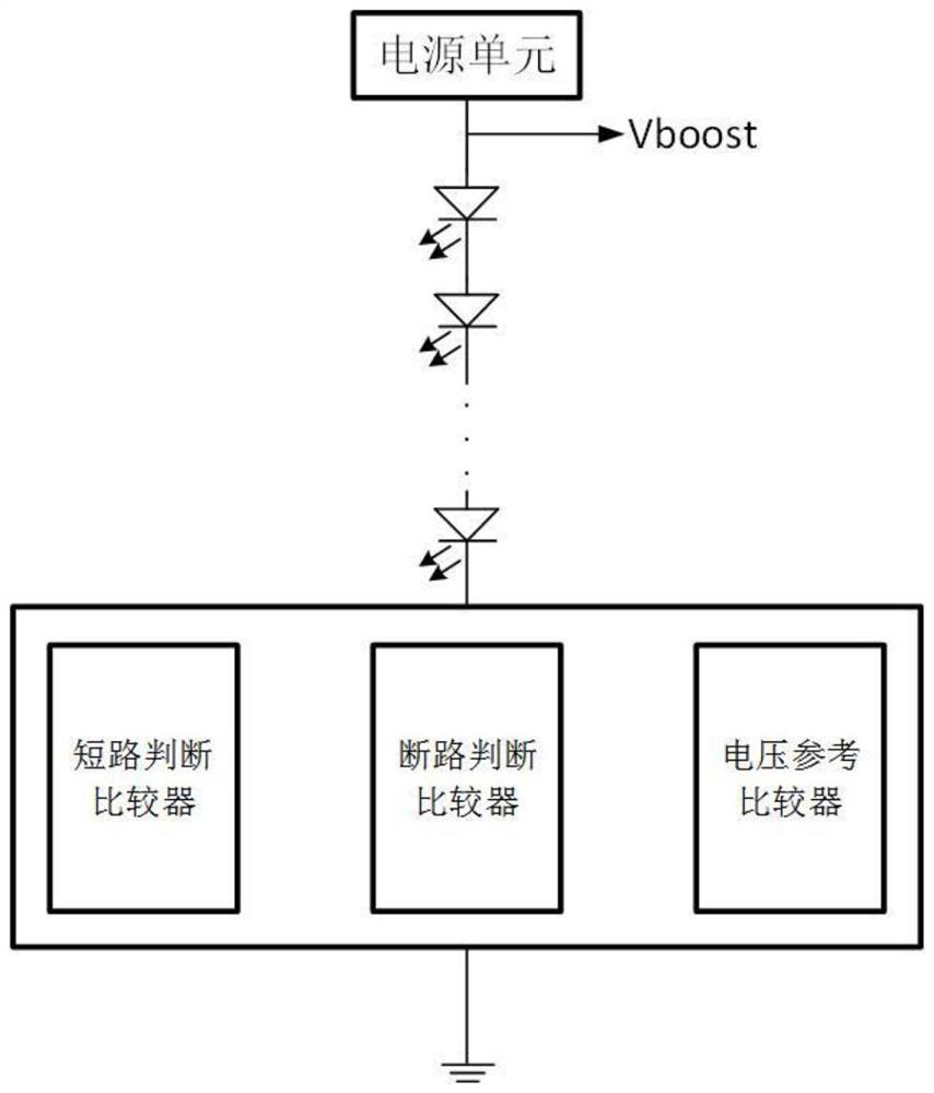
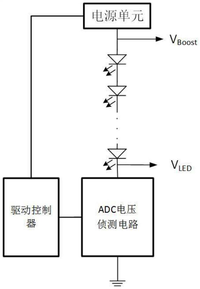
[0025] according to image 3 As shown, the LED backlight matrix drive circuit with voltage regulation unit of the present invention includes a power supply unit, LED light strings, ADC voltage detection circuit and a drive controller.

[0026] In this embodiment, the ADC voltage detection circuit is used to detect the voltage value V of the negative terminal of the LED light string led For detection, the negative terminal voltage value V will be obtained led Accurate measurement value, the ADC sampling module in the ADC voltage detection circuit can measure the voltage value V of the negative terminal of the LED light string led It is converted into a voltage numerical code and output to the drive controller.

[0027] In this embodiment, for the negati...


PUM


Abstract

The invention discloses an LED backlight driving circuit with a voltage regulation unit. The LED backlight driving circuit comprises a power supply unit, an LED lamp string, an ADC voltage detection circuit and a driving controller, the ADC voltage detection circuit is used for detecting a voltage value Vled of the negative end of the LED lamp string, and an ADC sampling module in the ADC voltage detection circuit can convert the measured voltage value Vled of the negative end of the LED lamp string into a voltage value code; a first threshold value V1 and a second threshold value V are set according to numerical coding of a negative end voltage value Vled measured by the ADC sampling module; when the numerical value code of the negative end voltage value Vled measured by the ADC sampling module is greater than or equal to a first threshold V1, it is judged that the LED lamp string has a short-circuit fault; and when the numerical value code of the negative end voltage value Vled measured by the ADC sampling module is smaller than a second threshold value or equal to V2, it is judged that the LED lamp string has an open circuit fault.

Description

technical field [0001] The invention relates to the technical field of communication, in particular to an LED backlight driving circuit and a method for detecting and adjusting a driving voltage thereof. Background technique [0002] Liquid crystal display (LCD) is the largest screen display application in modern display panels. The liquid crystal material used in LCD panels cannot emit light by itself, and needs to provide display light through a backlight source. LED backlight has the advantages of energy saving, environmental protection, and high performance, and is widely used in LCD display panels. The performance of LED backlight driving circuits is crucial to LCD display panels. The current LED backlight driving circuits pass The voltage value of the negative terminal of the LED light string V led Detect, and then judge the state of the LED light string through the driver chip, including judging the three states of the light string short circuit, short circuit, and v...

Claims


Application Information

Patent Timeline
Patent Type & Authority Applications(China)
IPC IPC(8): G09G3/34H05B45/30H05B45/50
CPCG09G3/3406H05B45/30H05B45/50Y02B20/30
Inventor 阳冠欧金慧娇
Owner X-SIGNAL INTEGRATED CO
Why Eureka
Try Eureka