
Holding device for mating element

A technology for holding devices and components, used in vehicle parts, bicycle accessories, transportation and packaging, etc., which can solve problems such as installation difficulties

Pending Publication Date: 2022-03-11
ROBERT BOSCH GMBH
View PDF8 Cites 0 Cited by
  • Summary
  • Abstract
  • Description
  • Claims
  • Application Information

AI Technical Summary

Problems solved by technology

Usual configuration of holding means in two different elements (these two elements hold or contact the accumulator on opposite elongate ends), when no connecting element is provided between said two elements, additionally make installation in frame interiors difficult

Method used


Image

  • Holding device for mating element
  • Holding device for mating element
  • Holding device for mating element

Examples


Embodiment Construction

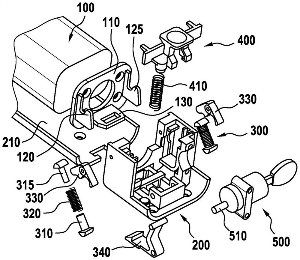
[0023] according to figure 1 The exploded view of FIG. 1 shows the components used to implement the invention. Here, this embodiment is only one of several possibilities.

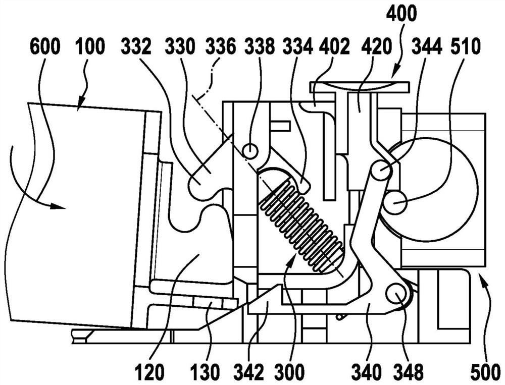
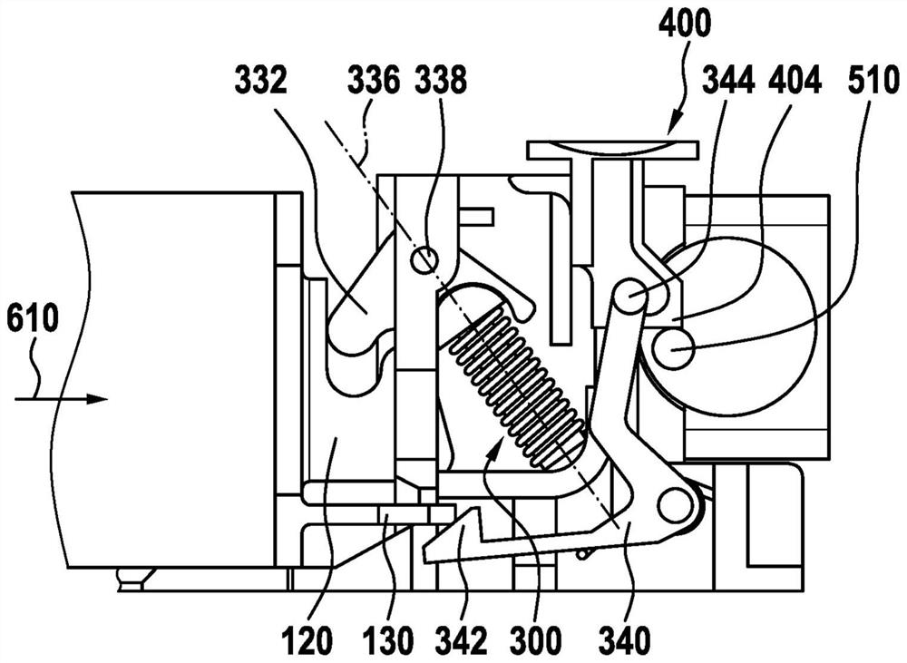
[0024] figure 1 A holding device 200 for an energy store 100 or accumulator is shown. Such a holding device can be used in various applications, for example in electric bicycles, tools, household appliances or toys. However, the invention should not be limited to holding accumulators. Rather, the invention is intended to enable the possibility of one-sided fastening of the counterpart element, ie the device in general, without the need for clamping on both sides. In this case, the counterpart element is clamped onto the holding device by means of the solution of the rotatable hook which will also be described and in particular clamped by means of an additional locking element. The counterpart element is thus blocked against removal. The spring connected to the hook allows not only an additional clampi...


PUM


Abstract

The holding device (200) according to the invention has at least one rotatable first rocker arm element (330) mounted at a first rotational point (338). The rocker arm element (330) is connected to a spring element (300) which can be tensioned by means of a spring (320). Furthermore, the rocker arm element (330) has a first hook (332) which can be in a first position and a second position. In the first position, a first hook (332) of the rocker arm element can engage in a receptacle (135) of the counterpart element for holding, such as a counterpart hook (120) or groove. In the second position, the first hook (332) of the rocker arm element in turn releases the counterpart element such that the counterpart element can be removed from the holding device (200). The inventive feature of the configuration of the retaining device is that the first rotational point of the support of the rocker arm element (330) lies outside the axis of the spring (320). This particular arrangement of the spring element (300) with respect to a supported first rotational point of the rocker arm element (330) makes it possible for a change from the first position to the second position to generate a displacement of the spring axis (336) from one side of the rotational point to the other side of the rotational point by means of a rotation of the rocker arm element (330). Wherein a spring (320) of the spring element (300) can be tensioned in one position and substantially relaxed in the other position.

Description

technical field [0001] The invention relates to a holding device for holding a counter element, in particular an energy store. Background technique [0002] There is a desire in various fields to use releasable holding devices in order to temporarily connect two elements to each other or to lock a device on the holding device. Especially when batteries are used in electrically propellable bicycles, it is expedient to remove the energy store mounted, for example, on or in the frame, in order to recharge it elsewhere. [0003] Conventional batteries for electric bicycles are currently still fastened to the frame of the bicycle in a holding device. Here, too, mounting of the holding device on the frame is possible without problems for a person not skilled in the art, since the user can access the frame from all sides. Installation is also somewhat more complex for a person skilled in the art when the battery holder is accommodated inside the frame, as is increasingly being pr...

Claims


Application Information

Patent Timeline
Patent Type & Authority Applications(China)
IPC IPC(8): B62J43/28B62J43/13B62J9/30B62M6/90
CPCB62J43/28B62J43/13B62J9/30B62M6/90Y02T10/70
Inventor P·库纳特
Owner ROBERT BOSCH GMBH
Learn More